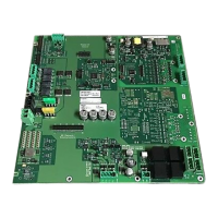
Periphery board (500p) FCI2017
2
34 | 46
2.5.1 Wiring the NAC circuits
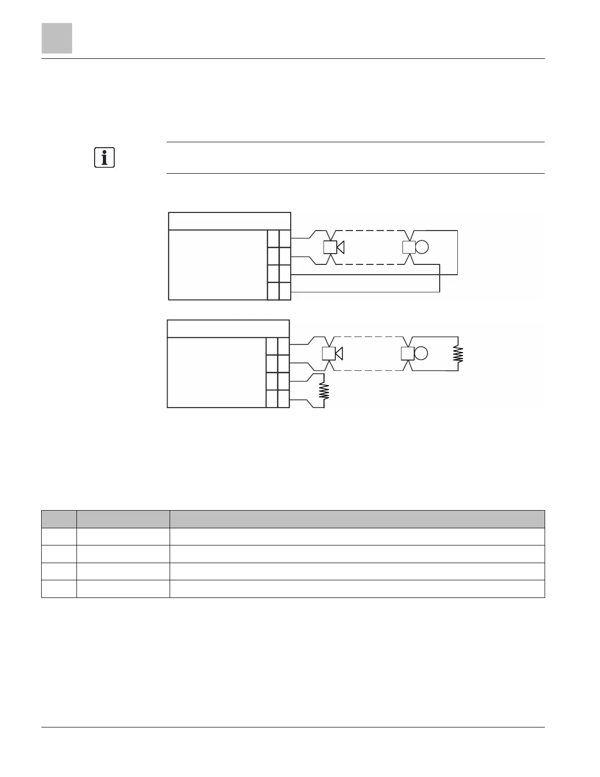
The following wiring diagrams show how to connect notification devices to the circuit,
either as class A (style Z) or class B (style Y) circuit. For class A, no end-of-line resistor
is needed. It is built into the circuit.
To ensure proper functioning, the
jumpers must be set correctly for class A/B
selection.
In the diagrams below, polarity is shown in activated condition.
Notification appliance circuit supervised and power limited.
Figure 9: X601: Class A (style Z) supervised output connection
Figure 10: X601: Class B (style Y) supervised output connection
* EOL resistance must be connected during non-use.
EOL resistance: 2.4 kΩ, 0.5 W
2.5.2 X601 terminal block – NAC 1 class A / NAC 1-1 class B / NAC
1-2 class B
Pin Designation Description
4 NAC1-1 (+) Positive feed for notification appliances for NAC 1 class A or NAC 1-1 class B
3 NAC1-1 (-) Return feed for notification appliances for NAC 1 class A or NAC 1-1 class B
2 NAC1-2 (+) Positive feed for notification appliances for NAC 1 class A or NAC 1-2 class B
1 NAC1-2 (-) Return feed for notification appliances for NAC 1 class A or NAC 1-2 class B
Admissible cable cross-section: 1 x 12…18 AWG or 2 x 16…18 AWG
X601
1
NAC1-2
+
NAC1-2
2
3
4
-
+
-
NAC1-1
NAC1-1
X601
1
NAC1-2
+
NAC1-2
2
3
4
-
+
-
NAC1-1
NAC1-1
+
-
*
EOL