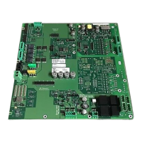
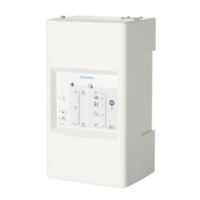
Periphery board (250p) FCI2016
1
14 | 46
You will find information on the installation in the following documents:
● A6V10315015 for Desigo
● A6V10333409 for Cerberus PRO
You will find information on the configuration in the following documents:
● A6V10315023 for Desigo
● A6V10333423 for Cerberus PRO
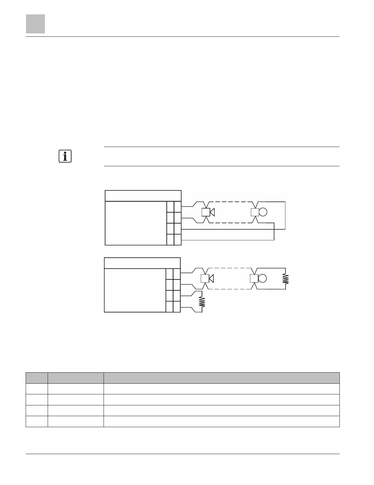
1.5.1 Wiring the NAC circuits
The following wiring diagrams show how to connect notification devices to the circuit,
either as class A (style Z) or class B (style Y) circuit. For class A, no end-of-line resistor
is needed. It is built into the circuit.
To ensure proper functioning, the jumpers must be set correctly
selection.
In the diagrams below, polarity is shown in activated condition.
Notification appliance circuit supervised and power limited.
Figure 3: X601: Class A (style Z) supervised output connection
Figure 4: X601: Class B (style Y) supervised output connection
* EOL resistance must be connected during non-use.
EOL resistance: 2.4 kΩ, 0.5 W
1.5.2 X601 terminal block – NAC 1 class A / NAC 1-1 class B /
NAC 1-2 class B
Pin Designation Description
4 NAC1-1 (+) Positive feed for notification appliances for NAC 1 class A or NAC 1-1 class B
3 NAC1-1 (-) Return feed for notification appliances for NAC 1 class A or NAC 1-1 class B
2 NAC1-2 (+) Positive feed for notification appliances for NAC 1 class A or NAC 1-2 class B
1 NAC1-2 (-) Return feed for notification appliances for NAC 1 class A or NAC 1-2 class B
Admissible cable cross-section: 1 x 12…18 AWG or 2 x 16…18 AWG
X601
1
NAC1-2
+
NAC1-2
2
3
4
-
+
-
NAC1-1
NAC1-1
X601
1
NAC1-2
+
NAC1-2
2
3
4
-
+
-
NAC1-1
NAC1-1
+
-
*
EOL