en Commissioning
Intended use
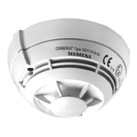
The linear smoke detector detects smoke and is suited for
fire detection in large storage and factory halls, also with
complex ceiling constructions. It consists of the detector
itself and a reflector placed opposite the detector.
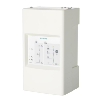
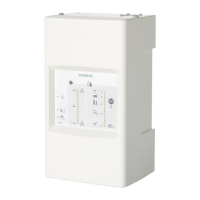
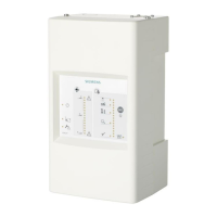
Setup and function of the adjustment set
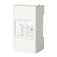
Commissioning is ensured by means of an adjustment set
consisting of an adjustment device, alarm test filter,
mounting chain, the sighting system and connection
cables.
The adjustment device automatically detects whether a
new detector or an already initialized one has been
connected.
The step-by-step operation of the adjustment device
during commissioning is ensured by the right button below
the display.
The display illumination can be activated by pressing the
left button.
When not used, the adjustment device will switch off
automatically after 5 minutes.
The adjustment device is operated with a 9V battery
located in a shaft at the back of the device.
2 labels (Fig. 11), for entering measurements during
commissioning or checking, are enclosed in the hood of
the FDL241-9. These measurements serve as a basis for
troubleshooting when periodically checking the FDL241-9.
Commissioning the detector
Procedure
1. Parameter setting
2. Installing the detector unit
3. Installing the detector heating unit in the detector
(option)
4. Installing the filter in the detector (option)
5. Commissioning the adjustment device
6. Verifying the signal level and distance
7. Roughly adjusting the detector optics (option)
8. Fine-tuning the detector optics
9. Initializing the detector
10. Carrying out detector tests
These steps are described in detail in the chapters below.
Parameter setting
Parameter setting depends on the detector line type
(FDnet or collective).
Detector line type FDnet
The parameter set is configured via the control unit or the
line test device. Use the documentation of the control unit
or the line test device.
Detector line type collective
The parameter set is selected by using the DIP switches
(Fig. 1, [1]).
– Select the desired parameter set with the switches
(see table below).
Collective
(DIP-Switch)
Parameter set
Alarm at n%
attenuation
S1 S2 S3
S4
S5
S6
on off off off Standard with open line
65%
off on off off Standard with BS alarm
65%
on on off off Sensitive with open line
50%
off off on off Sensitive with BS alarm
50%
on off on off Sensitive fast with open line
30%
off on on off Sensitive fast with BS alarm
30%
Installing the detector unit
WARNING
Danger of falling!
Bodily injury
• Always use a secured ladder or lifting platform for
the mounting work.
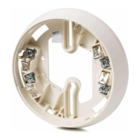
1. Place the detector unit (Fig. 2, [1]) with the LED pointing
downwards into the base (Fig. 2, [2]).
2. Fix the detector unit in the base using 4 screws
(Fig. 2, [3]).
The screws (Fig. 2, [3]) must be tightened as far as
possible!
Installing the detector heating unit in the detector
(option)
In case of danger of moisture condensation, it is
necessary to install a detector heating unit (Fig. 3).
External power supply (24V) is required.
1. Place the heating unit in the detector unit.
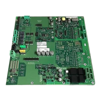
2. Connect the heating unit to the printed circuit board.
Installing the filter in the detector (option)
Depending on the measuring distance between the
detector and the reflector, or the lighting conditions in the
room, respectively, a filter must be optionally built in the
detector unit.
There are the following types of filter:
– Short-distance filter (depending on the measuring
distance between the detector and reflector)
– Extraneous light filter (depending on the lighting
conditions in the room)
Procedure
1. If required, select a short-distance filter or an
extraneous light filter in accordance with the project
planning specifications.
2. Place the filter (Fig. 4, [1]) in the detector unit.
3
Building Technologies PN A5Q00003832 008254_g_--_--
Fire Safety & Security Products 01.2009

 Loading...
