EasyManuals Logo

Siemens FN2012-A1 User Manual

Siemens FN2012-A1
34 pages
To Next Page IconTo Next Page
To Previous Page IconTo Previous Page
Page #25 background imageLoading...
Page #25 background image
Pin assignment
s
'POWER' connector strip
6
25 | 34
Building Technologies
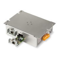
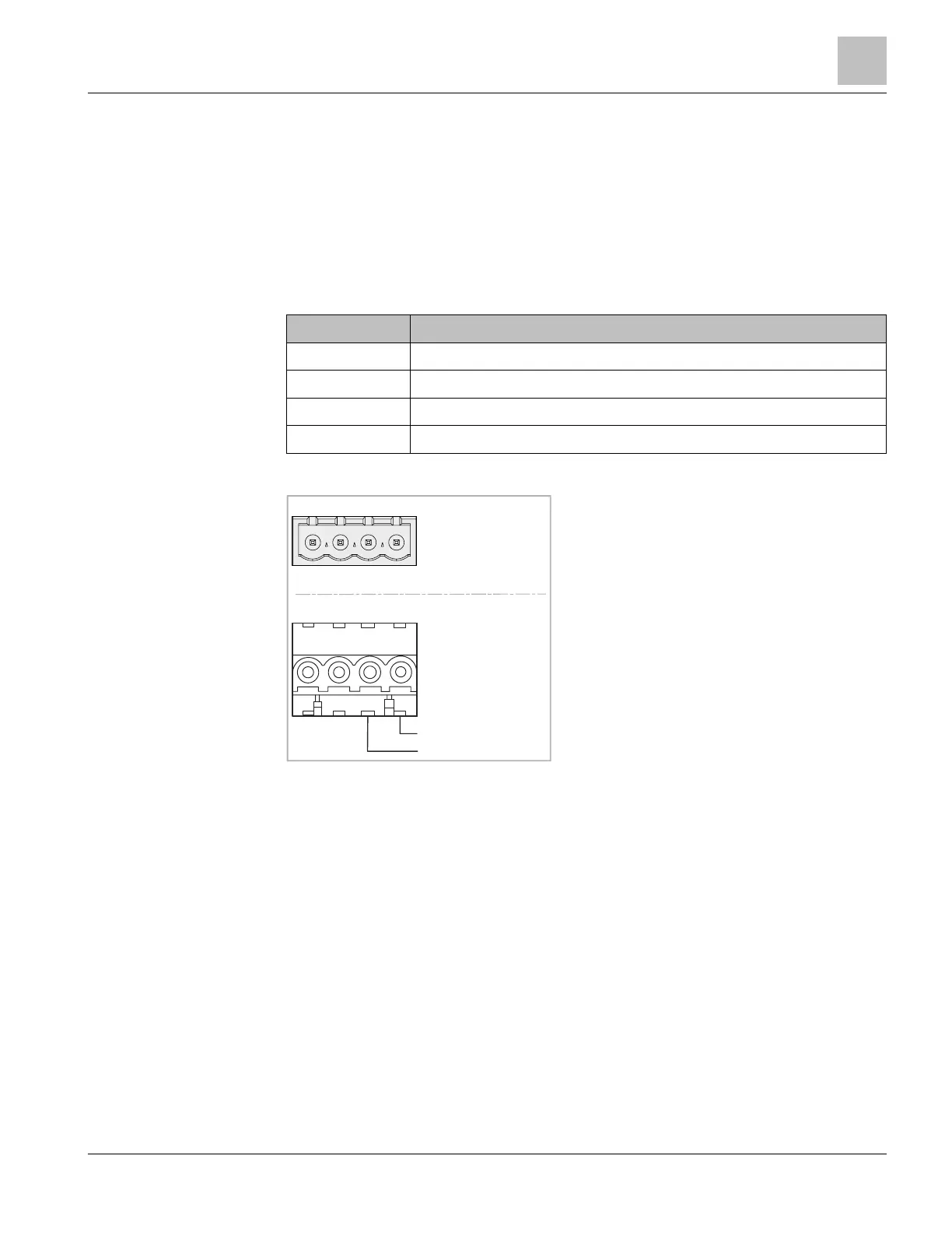
A6V10407862_d_en_
--
Siemens Industry, Inc.
2018
-
09
-
6 Pin assignments
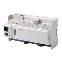
6.1 'POWER' connector strip
The 'POWER' connector is only needed if the supply is not possible via the MoNetBus
or PoE. This is generally only the case if the Ethernet switch (modular) is installed
remotely in another device. The power supply must be a DC 24 V power supply
featuring regulated and power-limited output that has been approved for fire alarm
signal applications.
Designation Description
A+ Supply input 1 (+DC 24 V)
A- Common supply input 1 (DC 0 V)
B- Not connected
B+ Not connected
Admissible cable cross-section: AWG 24...AWG 12 / 0.2...2.5 mm²
A+A-B-B+
POWER
+24V
GND
Terminal Plug
Connector FN2012
Supply input

Other manuals for Siemens FN2012-A1

Questions and Answers:

Question and Answer IconNeed help?

Do you have a question about the Siemens FN2012-A1 and is the answer not in the manual?

Siemens FN2012-A1 Specifications

General IconGeneral
BrandSiemens
ModelFN2012-A1
CategoryNetwork Router
LanguageEnglish

Related product manuals