Issued by
Siemens Industry, Inc.
Smart Infrastructure
8 Fernwood Road
Florham Park, NJ 08932
Tel. +1 973-593-2600
© Siemens Industry, Inc., 2019
Technical specifications and availability subject to change without notice
Doc No. A6V10333726_c_en_-- 100935693 A5Q00041959
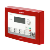
Fig 4
1. Insert the loop line and external power wire through the floor repeater display.
2. Mark the position for the 4 installation holes on flat wall (Fig. 2), drill the holes, put expansion bolts in and insert the
screws leaving a small gap for hanging the display.
3. Hang the floor repeater display over those screws through installation holes.
4. Open the front panel (Fig. 4/5), tighten the screws and make sure the display is fixed firmly.
5. Connect cables to terminals referring to the connection diagram (Fig. 3). Correctly set the internal 120Ω EOL
resistor referring to the section “EOL Resistor”.
6. Close the front panel.
FSD connects to separate power supply, which needs to be UL Listed for Fire Safety Use and Power
Limited.
Dimension (mm)
Technical data
Operating voltage 24 VDC nominal / 19…28 VDC
Operating current (quiescent) 60 mA
Activation current 70 mA
Operating temperature 0...+49 °C
Humidity ≤93% rel.
Communication protocol UFP (RS485-BUS)
Connection terminals 14-18 AWG
Color Black / Red
Operating location Indoor / dry
Details for ordering