Building Technologies / HVAC Products 4 319 2685 0 h M4626 28.10.2005 9/10
de
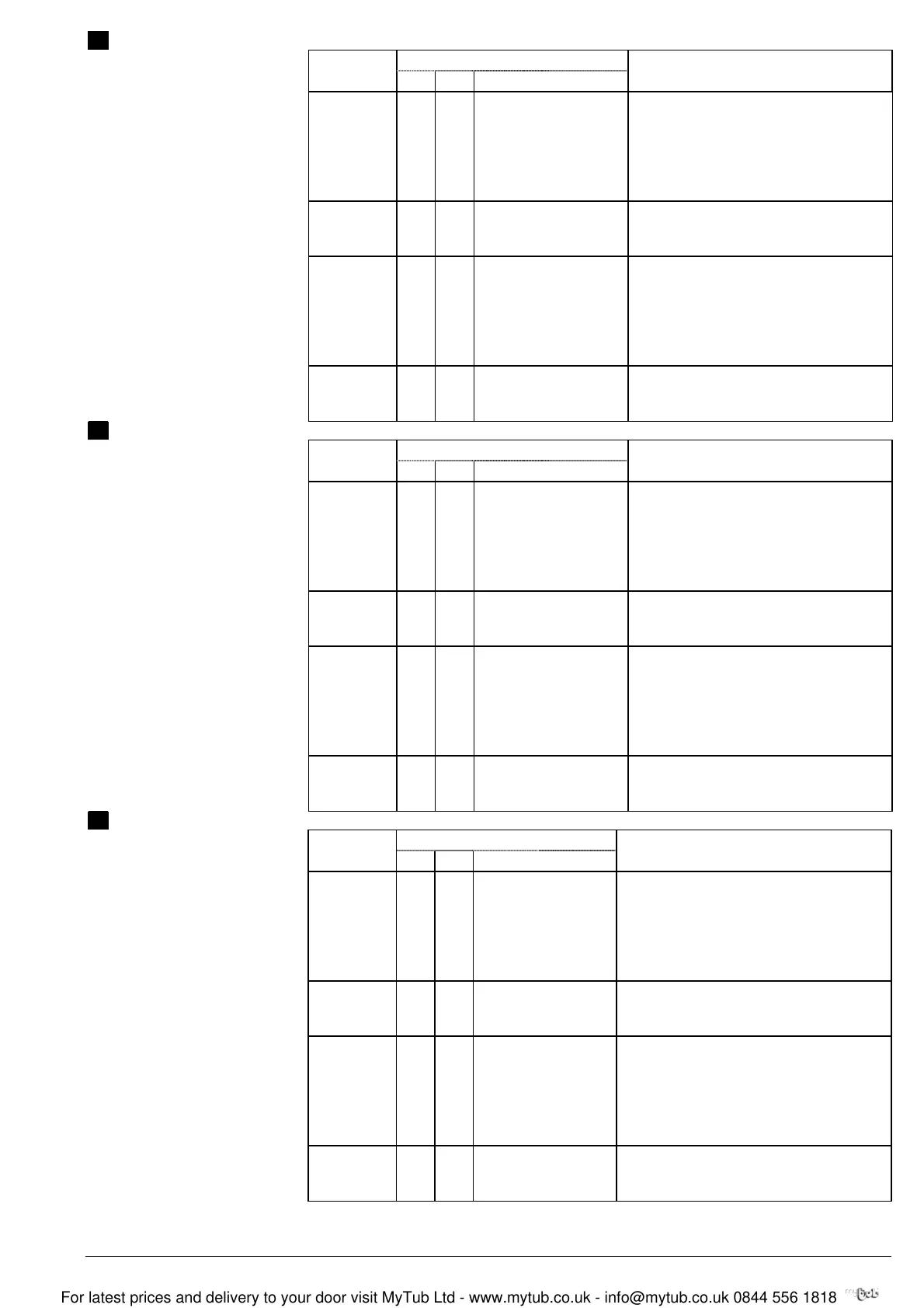
Kabel
Kabelbezeichnungen
Anschluss
Code Nr. Farbe Akürzung
Bedeutung
Antriebe G 1 rot RD System Potential AC 24 V
AC 24 V G0 2 schwarz BK Systemnull
Y1 6 violett VT Stellsignal AC 0 V "Uhrzeigersinn"
Y2 7 orange OG Stellsignal AC 0 V "Gegenuhrzeigersinn"
Y 8 grau GY Stellsignal DC 0...10 V, 0...35 V
U 9 rosa PK Stellungsanzeige DC 0...10 V
Antriebe N 4 blau BU Nullleiter
AC 230 V Y1 6 schwarz BK Stellsignal AC230 V, Uhrzeigersinn
Y2 7 weiss WH Stellsignal AC 230 V,Gegenuhrzeigersinn
Hilfsschalter Q11 S1 grau/rot GYRD Schalter A Eingang
Q12 S2 grau/blau GYBU Schalter A Ruhekontakt
Q14 S3 grau/rosa GYPK Schalter A Schliesskontakt
Q21 S4 schwarz/rot BKRD Schalter B Eingang
Q22 S5 schwarz/blau BKBU Schalter B Ruhekontakt
Q24 S6 schwarz/rosa BKPK Schalter B Schliesskontakt
Rückführ- a P1 weiss/rot WHRD Potentiometer 0...100 % (P1-P2)
potentimeter b P2 weiss/blau WHBU Potentiometer Abgriff
c P3 weiss/rosa WHPK Potentiometer 100...0 % (P3-P2)
en
Cable
Wire designations
Connecting
Code No. Color Abbreviation
Meaning
AC 24 V G 1 red RD System potential AC 24 V
Actuators G0 2 black BK System neutral
Y1 6 purple VT Actuating signal AC 0 V "clockwise"
Y2 7 orange OG Actuating signal AC 0 V "anticlockwise"
Y 8 gray GY Actuating signal DC 0...10 V, 0...35 V
U 9 pink PK Position indication DC 0...10 V
AC 230V N 4 blue BU Neutral
Actuators Y1 6 black BK Actuating signal AC 230 V, "clockwise"
Y2 7 white WH Actuating signal AC 230 V, "anticlockwise"
Auxiliary switch Q11 S1 gray/red GYRD Switch A input
Q12 S2 gray/blue GYBU Switch A normally closed contact
Q14 S3 gray/pink GYPK Switch A normally open contact
Q21 S4 black/red BKRD Switch B input
Q22 S5 black/blue BKBU Switch B normally closed contact
Q24 S6 black/pink BKPK Switch B normally open contact
Feedback a P1 white/red WHRD Potentiometer 0...100 % (P1-P2)
potentiometer b P2 white/blue WHBU Potentiometer pick-off
c P3 white/pink WHPK Potentiometer 100...0 % (P3-P2)
fr
Câble
Désignation des câbles
Câbles de
raccordement
Code No. Couleurs Abbreviation
Signification
servo-moteurs G 1 rouge RD potentiel du système AC 24 V
AC 24 V G0 2 noir BK zéro du système
Y1 6 violet VT signal de commande AC 0 V "sens horaire"
Y2 7 orange OG signal de comm. AC 0 V "sens anti-horaire"
Y 8 gris GY signal de commande DC 0...10 V, 0...35 V
U 9 rose PK signal de position DC 0...10 V
servo-moteurs N 4 bleu BU neutre
AC 230V Y1 6 noir BK Signal de commande AC 230 V "sens horaire"
Y2 7 blanc WH Signal de commande AC 230 V "sens anti-horaire"
commutateurs Q11 S1 gris/rouge GYRD commutateur A entrée
auxiliaires Q12 S2 gris/bleu GYBU commutateur A contact de repos
Q14 S3 gris/rose GYPK commutateur A contact de travail
Q21 S4 noir/rouge BKRD commutateur B entrée
Q22 S5 noir/bleu BKBU commutateur B contact de repos
Q24 S6 noir/rose BKPK commutateur B contact de travail
potentiomètre a P1 blanc/rouge WHRD potentiomètre 0...100 % (P1-P2)
de retour b P2 blanc/bleu WHBU potentiomètre curseur
c P3 blanc/rose WHPK potentiomètre 100...0 % (P3-P2)
For latest prices and delivery to your door visit MyTub Ltd - www.mytub.co.uk - info@mytub.co.uk 0844 556 1818
 Loading...