Do you have a question about the Siemens Desigo RXC20.1 and is the answer not in the manual?
Controllers can function as universal I/O modules for building automation systems.
Room controller functions depend on selected application, parameters, and I/O configuration.
RXC20, RXC21, RXC22 controllers differ in the number of outputs provided.
Specifies quantity, product name, type code, and application when ordering.
Details compatibility with QAX room units and other Siemens field devices.
Optional terminal covers protect connections from physical contact and dirt.
Details about detachable plug-in terminals and wiring separation for safety.
Explains how RXC controllers communicate via LONWORKS® bus and PPS2 interfaces.
Describes the service LED's status indication and the service pin's identification role.
Guidelines for disposing of the electronic equipment according to WEEE directive.
Refers to installation guides for LONWORKS® bus and cable dimensioning.
Details for rail mounting and surface mounting the room controllers.
Covers voltage, frequency, inputs, and measured value input specifications.
Details for AC 24 V triac outputs and relay outputs (Q14, Q24, Q34, Q44).
Information on room unit interfaces, LONWORKS® bus, and PPS2 protocols.
Details on terminal types, conductor sizes, and protection standards.
Specifies operating, transport conditions, and relevant product/EMC standards.
Provides information on RoHS compliance and environmental declarations.
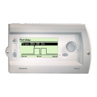
Details on commissioning using the RXT10 tool and the procedure.
How 'Appl.' and 'Loc.' fields are used for controller identification during commissioning.
How the RXT10 tool allows interrogation of inputs and control of outputs for testing.
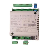
Detailed terminal assignments and descriptions for the RXC20 model.
Detailed terminal assignments and descriptions for the RXC21 model.
Detailed terminal assignments and descriptions for the RXC22 model.
Diagram showing connections for field devices, room unit, and power supply.
Important notes on fan operation, external fuses, and device compatibility.
Guidelines for connecting multiple thermic actuators, including power amplifier use.
Prohibits mixing controller and power amplifier connections for actuators.
Provides detailed dimensions of the controller with and without terminal covers.
Diagram for drilling mounting holes on a surface.
| Type | Room controller |
|---|---|
| Power Supply | 24 V AC/DC |
| Digital inputs | 4 |
| Analog outputs | 2 |
| Inputs (total) | 8 |
| Protection class | IP20 |
| Communication Protocols | BACnet |
| Communication | RS-485 |
| Mounting | DIN rail mounting |
| Dimensions | 90 x 60 mm |
| Operating Temperature | 0…50 °C |
| Relative Humidity | <95 % r.H., non-condensing |