EasyManua.ls Logo

Siemens Desigo RXC21.1 User Manual

Siemens Desigo RXC21.1
16 pages
To Next Page IconTo Next Page
Page #1 background imageLoading...
Page #1 background image
CA2N3834en_09
2013-06-16
Building Technologies
s
3
834
Desigo™ RXC
Room controllers
RXC20.1 / RXC20.5
RXC21.1 / RXC21.5
RXC22.1 / RXC22.5
For fan-coil systems, chilled ceilings and radiators
with L
ONMARK® compatible bus communications
The RXC20, RXC21 and RXC22 room controllers are used for temperature control
in individual rooms.
For 2-pipe or 4-pipe fan-coil systems, with or without change-over
For chilled ceilings and radiators
Control of AC 24 V PDM
1)
thermic valve actuators, 3-position AC 24 V valve
and damper actuators, or electric heating coils
Volt-free relay contacts for fan control and electric heating coils
PI or PID control (depending on application)
Downloadable application software
L
ONMARK® compatible bus communications
For use in the Desigo building automation and control system
AC 230 V operating voltage
1) PDM = pulse/duration modulated
Question and Answer IconNeed help?

Do you have a question about the Siemens Desigo RXC21.1 and is the answer not in the manual?

Siemens Desigo RXC21.1 Specifications

General IconGeneral
Product TypeRoom controller
Power Supply24 V AC/DC
MountingDIN rail mounting
Degree of protectionIP20
Communication ProtocolKNX
Outputs3 relay outputs
Operating Temperature0…+50 °C
Operating voltage24 V AC/DC

Summary

Use and Product Versions

I/O Module Functionality

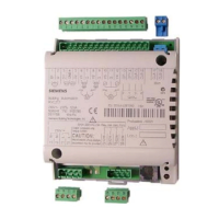
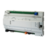
Describes how room controllers function as universal I/O modules for building automation systems.

Design and Components

Safety and Communication

Electrical Safety Warning

Crucial safety instruction to ensure power is off before handling plug-in terminals connected to mains voltage.

Device Communication Interfaces

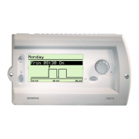
Describes LONWORKS bus and PPS2 interfaces for communication with other devices.

Technical Data Overview

Input and Output Specifications

Lists signal inputs, measured value inputs, triac outputs, and relay output specifications.

Connection Terminals and Diagrams

Connection Diagrams

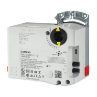
Illustrates wiring of field devices, room unit, LONWORKS bus, and power supply.

Mounting and Installation

Commissioning Notes

Provides guidance on commissioning using the RXT10 tool and function testing.

Related product manuals