GAMMA instabus
Technical Product Information
February 2013
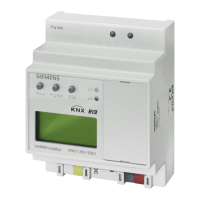
IP Controller N350E 5WG1 350-1EB01
Technical manual N350E, 4 Seiten Siemens AG
Infrastructure & Cities Sector, Building Technologies
Update: http://www.siemens.com/gamma © Siemens AG 2013 Control Products and Systems
Subject to change without further notice P.O. Box 10 09 53, D-93009 Regensburg
2.12.1.12/4
Slipping off bus connection blocks
(Figure 3)
- The bus connection block (D2) is situated on the top of
the device (D1).
- The bus connection block (D2) consists of two com-
ponents (D2.1 and D2.2) with four terminal contacts
each. Take care not to damage the two test sockets
(D2.3) by accidentally connecting them to the bus ca-
ble or with the screw-driver (e.g. when attempting to
unplug the bus connection block).
- Carefully put the screw-driver to the wire-inserting slit
of the bus connection block's grey component and
pull the bus connection block (D2) from the device
(D1).
Slipping on bus connection blocks (Figure 3)
- Slip the bus connection block onto the guide slot and
- press the bus connection block (D2) down to the stop.
Connecting bus cables
(Figure 3)
- The bus connection block (D2) can be used with single
core conductors Ø 0,6 ... 0,8 mm.
- Remove approx. 5 mm of insulation from the conduc-
tor (D2.4) and plug it into the bus connection block
(D2) (red = +, black = -).
Disconnecting bus cables
(Figure 3)
- Unplug the bus connection block (E1) and remove the
bus cable conductor (E1.4) while simultaneously wig-
gling it.
D2
D
D2
D2.
5 mm
D2
D2.4
D2.1
D2.2
D2
D2.3
Figure 3: Connecting and disconnecting bus wires
Slipping off / on auxiliary power connection block
- Follow the instructions for the bus connection block
when slipping off/on the auxiliary power connection
block.
Battery change
- Lift the battery case cover (A12) with a screw driver.
- Remove the battery with the battery holder.
- Separate the old battery carefully from the battery
holder to which it is glued.
- Insert the new battery in the battery holder and insert
both into the battery case. Ensure correct polarity (+
symbol) to achieve correct function of the real-time
clock.
- Close the battery case with the battery case cover
(A12).
- Battery type: Lithium CR 1/2 AA
Dimension Diagram
Dimensions in mm
b
90
44
55
b = 4 SU
1 Standard unit (SU) = 18 mm
General Notes
· The operating instructions must be handed over to the
client.
· A faulty device shall be returned with a Return Good
Note for Service provided by the appropriate Siemens
sales office.
· If you have further questions concerning the product
please contact our technical support.
' +49 (911) 895-7222
7 +49 (911) 895-7223
* support.automation@siemens.com
D1