19/22
Building Technologies CC1N7435en
HVAC Products 11.01.2007
Internal diagram and time diagram of the programming mechanisms
Legend
AL Alarm
AR Load relay with contact «ar»
AS Unit fuse
BR Locking relay with contact «br»
BV... Fuel valve
Dbr1 Wire link
EK... Lockout reset button
FR Flame relay
GP Gas pressure switch
HS Mains isolator
ION Ionization probe
L1 Lockout warning lamp
LP Air pressure switch
M Fan motor
MS Synchronous motor
R Control thermostat or pressurestat
SB Safety limit thermostat
W Limit thermostat or pressure switch
Z Ignition transformer
GP/
SB
W
R
HS
LN
0
I
M
LP
7435i01/0504
ION
Dbr1
Z
BV2
BV1
EK2
AL
EK1
2
10
8
4
5
7
9
1
11
6
3
1)
12
br
a
b
AS
I
a
b
ar
a
b
a
b
IV
FR
AR
fr
a
b
II
a
b
a
b
VIII
V
VI
IX VII
BR
a
b
a
bba
MS
L1
a
A Start position (switching on)
B Operating position of burner
C Operating position of programming mechanism or start
position
I...IX Cam switches
tw Waiting time
TSA Ignition safety time
T Total running time of programming mechanism
t1 Prepurge time
t3 Preignition time
t4 Interval «BV1 – BV2»
t10 Specified time for air pressure signal
t20 Interval up to self-shutdown of programming
mechanism
1) Resistance between terminal 3 and «N» must not
exceed 1.6 k
Ω
A
B
C
7435f04/0801
4
7
5
3
T = 81 s (40,5 s )
FR
AR
IX
VIII
VII
V
IV
II
I
b
a
tw
t10
t1
t3
TSA
t4
t20
VI
b
a
b
a
b
a
b
a
b
a
b
a
b
a
b
a
b
a
2)
2) Only with LGB21.130A27
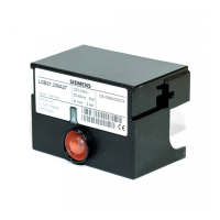
LGB21...

 Loading...


