Do you have a question about the Siemens LAL Series and is the answer not in the manual?
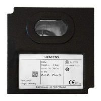
Details on the impact-proof and heat-resistance black plastic housing for the burner control.
Lists photoresistive, blue-flame, and silicon photocell flame detectors for burner controls.
Details on the SQN3 actuator for burner control applications.
Information on plug-in bases (AGM410490500, AGM13.1) for burner controls.
Specifies coaxial cable RG62, supplied by the customer.
Provides general specifications for the LAL burner control unit, including voltage, frequency, and power.
Details operating, storage, and transport conditions, including temperature, humidity, and altitude.
Describes the function and sequence for 2-stage expanding flame burners.
Explains the operation and sequence for modulating expanding flame burners.
Highlights safety features of the LAL burner control, including flame supervision checks.
Details the prepurge time phase where the air damper is fully open.
Describes the short preignition phase, including connection requirements.
Explains the long preignition phase with specific connection details for LAL1/LAL2/LAL3.
Defines the ignition safety time and its requirement for flame presence.
Covers the postignition time, including conditions for short preignition.
Details the interval between fuel valve operations or fuel valve and load controller.
Describes the interval after t5, where terminal 20 receives power and outputs are separated.
Explains the burner operation phase, including air damper control and flame loss lockout.
Describes the controlled shutdown sequence, including valve closure and sequence switch start.
Details the postpurge time, including air damper movement and terminal 11 activity.
Covers the permissible afterburn time, noting that a flame signal is still allowed.
Marks the end of the control program, where flame detection and simulation tests restart.
Explains lockout indication positions related to no input signal or specific fault types.
Describes the lockout indicator's function and how it shows startup sequence or postpurge status.
Illustrates connecting actuators without an end switch for the closed position.
Shows how to control the actuator using signals provided to terminal 17.
Details the control of fuel valves (BVx) using terminal 20.
Specifies wiring for LAL2 when air pressure supervision is not used.
Explains the manual startup procedure using buttons and the role of L3 indicator.
Shows load control and actuator connection for 2-stage expanding flame burners.
Illustrates load control and actuator connection for modulating expanding flame burners.
| Restart interlock | Yes |
|---|---|
| Category | Control Unit |
| Manufacturer | Siemens |
| Type | LAL |
| Series | LAL |
| Suitable burners | Gas burners |
| Frequency | 50/60 Hz |
| Safety time | 1…3 s |


 Loading...