EasyManua.ls Logo

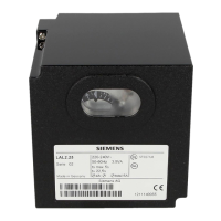
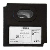
Siemens LAL3.25 User Manual

Siemens LAL3.25
24 pages
To Next Page IconTo Next Page
Page #1 background imageLoading...
Page #1 background image
CC1N7153en
21.09.2016
Building Technologies Division
7
153
Oil Burner Controls
LAL...
Oil burner controls
For oil atomizing burners of medium to large capacity
For multistage or modulating burners in intermittent operation
With or without air pressure supervision for checked air damper control
Flame supervision
– with photoresistive detector QRB
– or blue-flame detector QRC1
– or silicon photocell detector RAR9
Suitable for use with air heaters (WLE)
The LAL and this Data Sheet are intended for OEMs which integrate the oil
burner controls in their products!
Use
For the control and supervision of oil atomization burners
For burners of medium to high capacity
For intermittent operation (at least one controlled shutdown every 24 hours)
Can be universally used with multistage or modulating burners
Suited for use with stationary air heaters (WLE)
The flame supervision is ensured via a Photoresistive detectors QRBblue-flame
detectors QRC1 or Silicon photocell detectors RAR9.
LAL1 - Yellow- and blue-flame burners without air pressure supervision
LAL2 - Yellow-flame burners with air pressure supervision
LAL3.25 - For special applications, e.g. burners of incinerator plant
(for details, refer to «Type summary» and «Notes»)
Question and Answer IconNeed help?

Do you have a question about the Siemens LAL3.25 and is the answer not in the manual?

Siemens LAL3.25 Specifications

General IconGeneral
BrandSiemens
ModelLAL3.25
CategoryControl Unit
LanguageEnglish

Summary

Oil Burner Controls

Product Use and Applications

Details the applications and intended use of the oil burner controls.

Supplementary Documentation and Safety

Warning Notes

Essential safety precautions and warnings for handling and installation.

Installation and Mounting Guidelines

Guidelines for proper installation and mounting of the unit.

Electrical Connection and Commissioning

Flame Detector Electrical Connection

Guidance on connecting the flame detector for optimal signal transmission.

Commissioning and Safety Checks

Essential safety checks to perform during plant commissioning.

Engineering Notes

Technical notes for engineers regarding system integration and components.

Standards and Certifications

Compliance and Approvals

Details applied directives, standards, and conformity marks.

Product Lifecycle and Design

Mechanical Design and Housing

Information on the physical construction, materials, and housing features.

Type Summary and Timing Parameters

Legend of Times

Defines the various timing parameters used in the burner control sequences.

Accessories and Related Components

Flame Detectors and Actuators

Overview of compatible flame detectors and actuators.

Technical Data

General Unit Specifications

Key technical data for the LAL burner control unit.

Environmental and Storage Conditions

Details operating, storage, and transport environmental requirements.

Technical Data - Flame Supervision

Detector Current and Cable Lengths

Specifications for detector current and permissible cable lengths.

Detector Current Measurement Circuits

Schematics for measuring detector current.

Functionality and Operation Modes

2-Stage Flame Burner Operation

Describes the operational sequence for 2-stage expanding flame burners.

Modulating Flame Burner Operation

Describes the operational sequence for modulating expanding flame burners.

General Safety Features

Highlights the safety features integrated into the LAL controls.

Burner Control and Startup Logic

Control of Burner Operation

Details on controlling burner operation, including outputs and actuators.

Preconditions for Burner Startup

Conditions that must be met before a burner startup sequence can begin.

Startup Sequence Details

Preignition and Safety Time Parameters

Explains preignition, ignition safety time, and postignition phases.

Fault Handling and Lockout Indication

Lockout Causes and Indicator Symbols

Explains lockout causes, symbols, and indicator behavior.

Connection Diagrams

LAL1 Wiring Diagram

Wiring diagram for the LAL1 model.

Connection Diagrams (Continued)

LAL2/LAL3 Wiring Diagram

Wiring diagram for LAL2 and LAL3 models.

Sequence Diagram Overview

Control Output Signals Over Time

Visual representation of control output signals over time.

Connection Examples

Actuator and Wiring Configurations

Illustrates specific connection configurations for actuators and wiring.

Semiautomatic Startup Configuration

Example setup for semiautomatic burner startup.

Connection Examples and Program Sequence

2-Stage Burner Load Control Example

Example of load control for 2-stage expanding flame burners.

Modulating Burner Load Control Example

Example of load control for modulating expanding flame burners.

Document Legend and Symbols

Component and Signal Legend

Defines components, signals, and symbols used throughout the document.

Legend (Continued) and Time Table

Lockout Indications and Time Table

Explains lockout positions and provides a timetable of operational times.

Product Dimensions

Physical Dimensions

Provides detailed physical dimensions of the burner control unit.

Related product manuals