EasyManua.ls Logo

Siemens LFL Series - User Manual

Siemens LFL Series
12 pages
Print Icon
To Next Page IconTo Next Page
Loading...
Technical Instructions
Document No. 7451US
LFL...
Rev. 2 November 15, 2004
LFL Series
Burner Flame Safeguard Control
The LFL… is a compact electro-mechanical
primary flame safeguard control designed to
provide burner sequencing, automatic igni-
tion and continuous flame monitoring fo
r
gas, oil, and dual fuel, single burner applica-
tions.
The LFL… is applicable for on-off, multi-
stage or modulating burners. The LFL… is
designed for direct main burner ignition,
intermittent or interrupted pilot operation.
The LFL… integrates the flame amplifier,
purge timer and sequencer in a single con-
trol. Flame supervision is accomplished
using UV sensor or flame rod detection.
Features
Primary flame safeguard control
Visual sequence indication
Optional combustion air blower control
Optional postpurge
Preignition interlock
Continuous flame monitoring,
including extraneous light detection
UV sensor functional test
Proven air switch function
Proven high fire purge interlock
Proven low fire ignition interlock
Direct main burner ignition,
intermittent or interrupted pilot operation
Integrated flame amplifier
UV sensor or flame rod detector
Lockout alarm terminal
Local and optional remote reset
Burner off – economy position
(fully closed air damper interlock)
Unit fuse and spare fuse provided
Contents
Control Interface .................................................2
Installation...........................................................2
Ordering information ...........................................3
Wiring base.........................................................3
Specifications .....................................................4
Specifications continued .....................................5
Description of oper controls ................................6
Ladder diagram external connections.................7
Sequence Dial OPERATION ..............................8
Sequence Dial FAULT and LOCKOUT...............9
Sequence Chart................................................10
Dimensions.......................................................11
11.15.2004
Siemens Building Technologies
HVAC Products
Question and Answer IconNeed help?

Do you have a question about the Siemens LFL Series and is the answer not in the manual?

Summary

Features

Control Interface

Installation

Ordering Information

Wiring Base

Specifications

General

General technical data including voltage, fuse, weight, power consumption, and mounting.

Terminal Ratings

Details the electrical connections and maximum loads for each terminal on the LFL unit.

Approvals

Lists the certifications and standards met by the LFL unit, including UL, CSA, FM, CE, and FCC.

Environmental Ratings

Specifies the operating conditions, vibration tolerance, and temperature/humidity limits for the LFL unit.

Flame Supervision with UV Sensor

Technical details on using UV sensors for flame detection, including voltage, signal requirements, and cable length.

Flame Supervision with Flame Rod

Technical details on using flame rods for flame detection, including voltage, signal requirements, and cable length.

Description of Operating Controls and Functions

Wiring Diagram

Sequence Dial - Operation

Sequence Dial - Fault and Lockout Indication

Program Sequence Chart

Dimensions

Overview

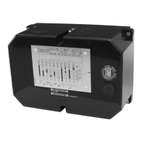
The Siemens LFL Series Burner Flame Safeguard Control is a compact electromechanical device designed for single burner applications using gas, oil, or dual fuel. It provides comprehensive burner sequencing, automatic ignition, and continuous flame monitoring. The control is suitable for on-off, multi-stage, or modulating burners and supports direct main burner ignition, as well as intermittent or interrupted pilot operation. It integrates the flame amplifier, purge timer, and sequencer into a single unit, with flame supervision achieved through UV sensor or flame rod detection.

Function Description:

The LFL control manages the entire burner start-up and operation sequence. It monitors various interlocks and conditions to ensure safe and efficient burner operation. Key functions include:

  • Burner Sequencing: Controls the precise timing of pre-purge, pilot trial for ignition (PTFI), main trial for ignition (MTFI), and post-purge phases.
  • Automatic Ignition: Initiates ignition based on programmed sequences, supporting direct main burner ignition, intermittent pilot, or interrupted pilot.
  • Continuous Flame Monitoring: Actively supervises the flame presence throughout burner operation, detecting flame failure or extraneous light.
  • Interlock Management: Integrates with various safety interlocks such as operating limit switches (OLS), low/high gas pressure (LGP/HGP) switches, low water switches (LWS), combustion air switches (CAS), and fuel proof of closure (POC) switches.
  • Actuator Control: Provides outputs to drive damper actuators to specific positions (high fire, low fire, fully closed) and receives feedback on their status.
  • Fault Detection and Lockout: Identifies fault conditions and initiates a lockout if safety parameters are not met, preventing burner operation until manually reset.

Important Technical Specifications:

  • Supply Voltage: 100 Vac -15% to 110 Vac +10% (50/60 Hz ±6%) or 220 Vac -15% to 240 Vac +10% (50/60 Hz ±6%).
  • Internal Fuse: 6.3 A (slow).
  • External Fuse: Maximum 10 A (slow).
  • Power Consumption: 3.5 VA.
  • Weight: LFL unit: 2.2 lb, Wiring base: 0.25 lb.
  • Mounting Orientation: No restrictions.
  • Terminal Ratings:
    • Terminal 1 (Line): Maximum 5 A total load.
    • Terminal 3 (Alarm): 1 A pilot duty.
    • Terminals 6 and 7 (Combustion Air Blower): Motor 4 FLA, 24 LRA or 1.6 A pilot duty.
    • Terminal 16 (Ignition Transformer): 4 A.
    • Terminal 17 (Pilot Fuel Valve): Motor 4 FLA, 24 LRA or 1.6 A pilot duty.
    • Terminal 18, 19 (Main Fuel Valve): Motor 4 FLA, 24 LRA or 1.6 A pilot duty.
  • Flame Supervision (UV Sensor QRA...):
    • Voltage (burner operation): 330 Vac ±10%.
    • Voltage (start-up phase): 380 Vac ±10%.
    • Required minimum UV sensor signal: 70 µA.
    • Typical UV sensor signal measurement: 100-450 µA.
    • Max. detector cable length: 300 ft (unshielded), 600 ft (shielded).
  • Flame Supervision (Flame Rod):
    • Voltage (burner operation): 330 Vac ±10%.
    • Voltage (start-up phase): 380 Vac ±10%.
    • Required minimum flame rod signal: 6 µA.
    • Typical flame signal measurement: 20-100 µA.
    • Short-circuit current: max. 0.5 mA.
    • Max. detector cable length: 250 ft (unshielded), 500 ft (shielded).
  • Environmental Ratings:
    • Vibration: 0.5G Environment.
    • Operation Temperature Range: -5°F to +140°F (< 95% relative humidity).
    • Storage Temperature Range: -58°F to +140°F (< 95% relative humidity).
    • Condensation, formation of ice, and ingress of water are not permitted.
  • Timing Descriptions (60 Hz operation; 50 Hz operation times are 20% longer):
    • Pre-purge time: 7.5 sec (LFL1.133), 26 sec (LFL1.333), 31 sec (LFL1.335), 55 sec (LFL1.635).
    • Pilot trial for ignition (PTFI): 2.5 sec (LFL1.133), 4 sec (LFL1.333, LFL1.335, LFL1.635).
    • Main trial for ignition (MTFI): 2.5 sec (LFL1.133), 4 sec (LFL1.333, LFL1.335, LFL1.635).
    • Interval from beginning of MTFI until release to modulation: 2.5 sec (LFL1.133), 10 sec (LFL1.333), 10.5 sec (LFL1.335), 12 sec (LFL1.635).
    • Post purge time: 12 sec (LFL1.133, LFL1.635), 15 sec (LFL1.333, LFL1.335).
    • Flame failure response time (FFRT): 1 sec.

Usage Features:

  • Visual Sequence Indication: An indicator dial visible through the front window provides symbolic information about the program sequence, fault type, and the point in the sequence where a fault occurred.
  • Lockout Indicator Light: A dedicated light indicates a lockout condition.
  • Reset Button: Integrated into the front window, pressing it resets the LFL during a lockout. Pressing it during normal operation will initiate a lockout (do not hold for more than 10 seconds to avoid damage).
  • Optional Combustion Air Blower Control: Provides terminals for controlling the combustion air blower, with options for immediate power or a 2-second delay, and continuous operation through post-purge.
  • Optional Postpurge: Allows for continued blower operation after burner shutdown to clear residual combustion products.
  • Preignition Interlock: Ensures safety conditions are met before ignition.
  • Extraneous Light Detection: The flame monitoring system can detect extraneous light, preventing false flame signals.
  • UV Sensor Functional Test: Includes a functional test for UV sensors to ensure proper operation.
  • Proven Air Switch Function: Verifies that combustion air is being provided.
  • Proven High Fire Purge Interlock: Ensures the actuator is at the high fire position during pre-purge.
  • Proven Low Fire Ignition Interlock: Ensures the actuator is at the low fire (minimum) position during ignition.
  • Lockout Alarm Terminal: Provides an output for an external alarm during lockout conditions.
  • Local and Optional Remote Reset: Allows for resetting the control either directly on the unit or via a remote switch.
  • Burner Off - Economy Position: Supports a fully closed air damper interlock following post-purge to minimize heat losses.
  • Unit Fuse and Spare Fuse Provided: Enhances reliability and simplifies maintenance.

Maintenance Features:

  • Modular Design: The LFL control unit is separate from the wiring base, facilitating easier installation and replacement.
  • Clear Wiring Base: The wiring base provides 24 terminals, 3 ground connections, and 3 neutral connections (connected to terminal 2), simplifying wiring and troubleshooting.
  • Diagnostic Indicator Dial: The indicator dial provides immediate visual feedback on the control's status and fault conditions, aiding in quick diagnosis.
  • Accessible Reset: The front-mounted reset button allows for easy manual resetting after a lockout.
  • Detailed Documentation: Comprehensive technical instructions and wiring diagrams are provided to assist with installation, operation, and troubleshooting.
  • Approvals: UL, CSA, FM, CE, and FCC compliant, ensuring adherence to safety and performance standards.

Siemens LFL Series Specifications

General IconGeneral
BrandSiemens
ModelLFL Series
CategoryControl Unit
LanguageEnglish

Related product manuals