Specifications continued…
Voltage – during burner operation
Voltage – during start-up phase (flame circuit check)
330 Vac ±10 %
380 Vac ±10 %
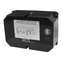
Required minimum UV sensor signal
Typical UV sensor signal measurement
70 µA
100-450 µA
Length of detector cable (run in a separate conduit from all other wiring)
- Unshielded wire
- Shielded cable, shield grounded to terminal 22
max. 300 ft
max. 600 ft
Flame
supervision
with
UV sensor
QRA...
Voltage at the flame rod – during burner operation
Voltage at the flame rod – during start-up phase (flame circuit check)
330 Vac ±10 %
380 Vac ±10 %
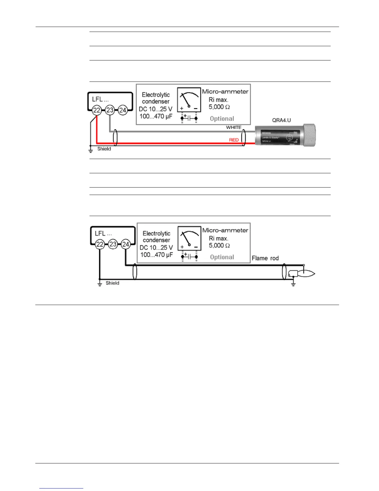
Required minimum flame rod signal
Typical flame signal measurement
6 µA
20-100 µA
Short-circuit current max. 0.5 mA
Length of detector cable (run in a separate conduit from all other wiring)
- Unshielded wire
- Shielded cable, shield grounded to terminal 22
max. 250 ft
max. 500 ft
Flame
supervision
with
Flame rod
Electrical connection notes for flame supervision
• It is important to minimize electrical disturbance and signal loss.
• Run flame signal wiring separate from all other wiring
• Observe the length of detector cable as indicated above
• The flame rod does not provide protection from electric shock
• Locate the ignition electrode(s) and flame rod such that the ignition spark cannot arc to the
flame rod (risk of electrical overload and damage to flame supervision circuit)
• When using the QRA..., grounding of terminal 22 is required
• Multiple UV sensors QRA... and/or flame rods can be connected in parallel
• If separate flame sensors are used for pilot and main flame supervision,
an interrupted pilot must be utilized
5/12
Siemens Building Technologies CC1N7451en
HVAC Products 11.15.2004

 Loading...