EPAC300-M50 SERIES USER’S MANUAL
AUGUST 2005 PAGE 5 OF 46
SECTION TITLE PAGE
8 CONTROLLER DOCUMENTATION -------------------------------------------- 33
8.1 Engineering Drawings and Part Numbers---------------------------------- 33
8.2 Product Identification ------------------------------------------------------------- 35
8.2.1 Model Number ----------------------------------------------------------------------- 35
8.2.2 Serial Number------------------------------------------------------------------------ 35
8.2.3 Date Code ----------------------------------------------------------------------------- 35
8.3 Part Identification------------------------------------------------------------------- 35
9 CONTROLLER INSTALLATION ------------------------------------------------ 36
9.1 Introduction--------------------------------------------------------------------------- 36
9.2 Handling ------------------------------------------------------------------------------- 36
9.3 Environmental ----------------------------------------------------------------------- 36
9.3.1 Humidity ------------------------------------------------------------------------------- 36
9.3.2 Heat ------------------------------------------------------------------------------------- 36
9.3.3 Electrostatic Discharge----------------------------------------------------------- 37
9.4 Module Installation----------------------------------------------------------------- 38
9.5 Controller Unit Installation ------------------------------------------------------ 38
9.5.1 Ventilation----------------------------------------------------------------------------- 38
9.5.2 Grounding----------------------------------------------------------------------------- 38
9.5.3 Wire Routing ------------------------------------------------------------------------- 40
10 WARRANTY--------------------------------------------------------------------------- 42
LIST OF FIGURES
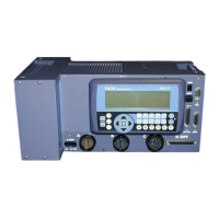
Fig 1 EPAC300-M50 Series Controller----------------------------------------------- 6
Fig 2 EPAC300-M50 Series Controller Layout ------------------------------------ 7
Fig 3 Port 2 “Y” Cable Block Diagram ---------------------------------------------- 10
Fig 4 Port 2 Adaptor Cable Block Diagram ---------------------------------------- 10
Fig 5 LCD Contrast Adjustment ------------------------------------------------------- 15
Fig 6 Expansion Option ------------------------------------------------------------------ 17
Fig 7 EPAC300-M50 Series Controller Exploded View ------------------------ 18
Fig 8 Modem Programming Straps -------------------------------------------------- 21
Fig 9 Recommended Connection, Data Cable Grounds and Shields ----- 40
 Loading...

