Do you have a question about the Siemens 7sg15 microtapp and is the answer not in the manual?
Overview of the MicroTAPP system's operation, features, and functional descriptions.
Introduction to the MicroTAPP system's general layout, operation, and human intervention.
Details on managing parallel transformer operation, circulating current, and TAPP method.
Functionality for offsetting voltage drops due to load changes using communication.
Details on advanced features for voltage regulation and transformer control, including tap spacing.
Procedure for managing transformer switch-out to maintain voltage stability and minimize impact.
Procedure for managing transformer switch-in to maintain voltage stability and minimize impact.
Configuration parameters for the MicroTAPP relay, covering site, transformer, and network data.
Electrical control points for tap change mechanisms, including local and remote options.
Integral control switches for manual/automatic and local/remote operation of the tap changer.
Monitoring voltage and current to prevent abnormal system voltages and protect equipment.
Monitoring tap changer operation for faults, runaway, and limit conditions.
Indications and measurements provided by the MicroTAPP relay for system monitoring.
Logging of fault, graphical, and event records with date and time stamps for analysis.
Details on communication ports, protocols, and compatibility with external systems.
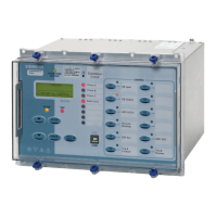
Overview of the MicroTAPP relay's fascia layout, including display, LEDs, and push buttons.
Operation and navigation using the keypad and LCD display for settings and data.
Interface for connecting PCs via RS232 for data access and settings configuration.
Entering and configuring relay settings for network, transformer, and tap-changer parameters.
Accessing readings for system values, loads, frequency, and tap-changer status.
Viewing recent tap-changer faults with descriptions and timestamps for troubleshooting.
Design and construction details for EMI screening, noise immunity, and component layout.
Description of connectors for relay inputs, outputs, and communication interfaces.
Detailed characteristics including energising quantities, circuit burden, and voltage control.
Measured and calculated electrical quantities (voltage, current, frequency) and their accuracies.
Parameters for basic voltage regulation, including target level, bandwidth, and initial delay.
Calibration of LDC based on substation capacity and voltage bias for load compensation.
Levels for preventing overcurrent, overvoltage, runaway, and out-of-limit tapping conditions.
Specifications for output contacts, including continuous, make-and-carry, and break ratings.
Accuracy specifications for measurements and influencing quantities like temperature.
Environmental withstand capabilities including temperature, humidity, and electrical disturbances.
Configuration of system-wide settings like active group, relay identifier, and time.
Configuration settings related to the transformer, including capacity, impedance, and voltage ratings.
Settings for the tap changer, such as number of taps, input type, and runaway detection.
Configuration of network parameters like transformer groups, power factor, and voltage control method.
Settings for voltage control parameters: target voltage, band, LDC, and delays.
Advanced configuration options for voltage and CT/VT location, tap spacing, and voltage adjustment.
Mapping functional outputs to hardware relays for alarms and control signal assignments.
Mapping functional inputs to hardware status inputs for control and monitoring purposes.
Configuration of communication parameters like station address, baud rate, and parity.
Options for managing stored data, including clearing event and fault records.
Settings for tap-changer maintenance counts, alarms, and reset functions.
Physical characteristics of ports, fiber optic cable types, and connection methods.
Configuration of relay settings, specifically focusing on the communications menu.
Technical data for fiber optic communication, including launch power, sensitivity, and distances.
Application of tap change control, including TAPP method and parallel transformer operation.
Setting system power factor for TAPP method, LDC compensation, and circulating current.
Application of MicroTAPP for parallel transformer operation and LDC in groups.
Management of network control operations, including switching transformers in and out.
Procedure for managing transformer switch-out to minimize voltage impact on the system.
Procedure for managing transformer switch-in to maintain voltage stability and minimize impact.
Considerations for using voltage transformers, including location and operational aspects.
Typical arrangements for tap change control schemes, including I/O allocations.
Description of standard and alternate status input ratings and mapping to functions.
Description of standard output relay ratings and mapping to functions.
Connections and monitoring for various tap position sender unit types.
Details on MPPC system cable requirements, connections, and termination.
Key tests to be carried out for on-site confirmation of relay operation.
Testing insulation resistance of various circuits (CT, VT, inputs, outputs) to earth.
Checking correct connections and operation of control signal inputs for tap changing.
Final checks for correct operation of the automatic voltage control scheme and tap changer.
Verifying protection functions related to tap position, runaway prevention, and signal integrity.
Performing operational checks and tests before the transformer is put on load.
Performing operational checks and VT calibration before the transformer is loaded.
Verifying correct operation of voltage control system, LDC, and parallel transformer control under load.
Fine-tuning settings like Basic, Bandwidth, and LDC for optimal system operation.
Accurate setting of system power factor for compensation and reliable relay function.
Tests to be carried out on the relay during normal operation to ensure accuracy and control.
Verifying the correct operation of the basic control level and voltage limits.
Calibrating LDC based on site load and checking its effect on voltage regulation.
Checking the operation of alarm contacts by simulating fault conditions.
| Frequency | 50/60 Hz |
|---|---|
| Communication Protocols | Modbus RTU |
| Protection Functions | Overcurrent, Earth Fault |
| Mounting | DIN Rail |
| Rated Current | 1A |


