7SG15 MicroTAPP Application Guide
1 Introduction
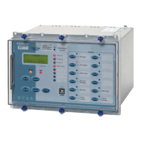
The comprehensive design of the MicroTAPP relay simplifies the design of a tap change control system allowing
a large reduction in the external wiring normally required. Application of the relay for voltage control of the most
complex networks is easily accomplished.
2 Voltage Standards
The allowable range of permissible voltage at each supply point determines to a large extent, the operational
voltages that can be applied at each voltage level on the network. Using typical voltage ranges it will be useful
here to examine the maximum typical design voltage drops that can occur across a distribution system at extreme
loading conditions.
For this example the network voltage levels are 33kV, 11kV and LV.
Table 1 lists voltage drops starting at the in-feed point, this example being only one of many, but used here for the
purpose of explanation. The tables use figures for fixed tap distribution transformers based on a nominal output
equivalent to the statutory voltage and off load adjustment in ±2.5% and ±5% steps. In practice the nominal
voltage of fixed tap transformers is higher than the statutory voltage, giving a fixed boost over the levels used in
this example.
% Voltage Difference (from
nominal)
At Source
Remote End
No
Load
Full
Load
No
Load
Full
Load
33/11kV Transformer
(Basic 100% used to offset
higher voltage system drop)
0 0 0 0
MV System
0 0 0 -8
LV System
0 -1 0 -7
Total
0 -1 0 -15
No load/Full load variation
1 15
Table 1
Under the conditions shown in Table 1 where a basic control of voltage is used to give a constant voltage at the
11kV busbar, a customer connected close to the 33/11kV source can receive a supply that varies by only 1%,
while a customer connected at a remote point on that network can receive a supply having a variation of some
15%.
Improved system utilisation can only be achieved and adequate voltage levels maintained if compensation for the
full load drop can be successfully applied to the voltage control system such that the no-load/full-load variation is
optimised.
2.1 Increasing the Network Capability
A method of Automatic Voltage Control (AVC) with Line Drop Compensation (LDC) has been used to offset the
effects of line drops due to the load current effect upon the line R/X characteristic in order to achieve a constant
voltage at the far end of a transmission line. This method is not practical for the distribution system where
customers are connected along the length of multiple feeders radiating from a single substation with each feeder
having a different load characteristic and length. The theoretical calculation of usable settings is, therefore,
difficult for a distribution network.
©2011 Siemens Protection Devices Limited Chapter 5 Page 3 of 21

 Loading...


