7SG15 MicroTAPP Description of Operation
©2013 Siemens Protection Devices Limited Chapter 1 Page 6 of 38
4 Description of operation
4.1 General
Operate
Time
Relay
Deadband
80% Volts
Initial
Delay
IDMTL
Initial
Delay
DTL
Initial
Delay
Figure 2
The MicroTAPP provides a system, at each point where voltage is regulated, that operates at all times with
minimal human intervention and is capable of optimal operation under various power network arrangements.
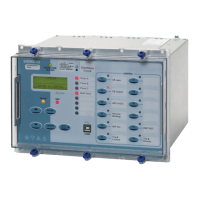
A diagram showing the general layout of the relay fascia is shown at the end of this section in appendix A.
When selected to ‘automatic’ mode, the voltage regulating relay controls the transformer tap changer. Voltages
which are outside set voltage limits (deadbands) automatically initiate the operation of the transformer tap
changer in order to restore the secondary voltage to normal.
When selected to ‘manual’ mode, the voltage can be regulated via the relay manual raise/lower control integral
switches. The application section of this document gives more information regarding other tap change controls
that may be incorporated into the voltage control scheme.
The operating characteristics of the voltage regulating relay are such that a raise or lower command will only be
issued after an initial time delay as set on the voltage regulating relay. A definite time characteristic or an
inversely related initial time characteristic is selectable for voltage in excess of the Relay Deadband . Figure 2
shows the characteristics for both types of time delay setting.
The MicroTAPP provides two initial time delays, a definite and an inverse characteristic. The inverse time delay is
dependant on the voltage deviation from the normal band and is defined by:-
Vtarget - Vmeasured
Vban

 Loading...


