7SG15 MicroTAPP Application Guide
5 MT1-102 Advanced Relay - Application Guide
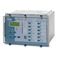
The advanced MicroTAPP relay (MT1-102) is available for applications where MW and MVar power flow is more
dynamic, for instance when applied to Generator step up Transformers or at embedded generation sites. It has
features that allow widely fluctuating loads to be accommodated on industrial supplies. Such loads are blast
furnaces, rolling mills and smelter plants. The voltage control point can be switched between HV and LV
depending upon the running arrangement of the plant. This is done by switching relay setting groups from the
plant status fed to the relay via hardwired inputs or via the communication.
This relay can be fed from a AVC VT and CT on the HV or LV side of the transformer. It can also be used for
single or three phase power transformers and allow reactive current compensation to be reduced to allow reactive
current to flow through the system. It is therefore suitable for transmission applications and can be manually
tapped to control MVar flow.
In all circumstances at a site where transformers are operated in parallel using the reactive circulating current
control scheme, all relays must be set to operate from a voltage source on one side of the transformers only. With
the MT1-102 relay this may be the directly measured voltage where the AVC VT is located, i.e. ‘normal’ or at the
other side where the voltage is calculated, i.e. a ‘virtual’ VT. The relays can then have their control point switched,
as demonstrated by the example below.
Application of the advanced settings is dependent upon particular operational situations. As an example consider
a network where a local generation scheme supplies local load network which is also supplied by a long line from
a remote source, Figures 4 and 5.
G
Load A
Load B Load C
Source
VCR
VCR
VCR
Figure 4
If the generation is active and the network is heavily loaded, voltage control is switched over to take control of the
incoming voltage at load site A (see Figure 4) while the generation is configured to maintain the voltage on the
local busbar. The incoming voltage at load sites B and C are supported by load site A and offset the line voltage
drop from the source. Under light loading or during generation down time the VCR at load site A would be
switched to take control of the voltage level at the local busbar.
VT
CT
MicroTAPP
Power Flow
Controlled
Network
'Virtual' VT
C
Figure 5
©2011 Siemens Protection Devices Limited Chapter 5 Page 9 of 21

 Loading...


