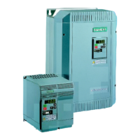
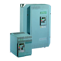
The Siemens MICROMASTER Eco and MIDIMASTER Eco are frequency inverters designed for controlling the speed of fans and pump motors, ranging from 0.75kW to 315kW. These operating instructions provide a quick and simple guide for commissioning the devices, with a more comprehensive Eco Reference Manual available for specific applications and a complete parameter list.
The Eco range of inverters offers variable frequency control for fan and pump motors, along with the ability to manage various other motor functions and limits. These functions are configured using parameters programmed via the integrated keypad.
System Control:
The inverters are typically controlled using the keypad or input/output terminals. For remote operation, an RS485 D-type connection on the front panel is available, with further details in the Eco Reference Manual. The output frequency, and consequently motor speed, can be controlled through digital or analog inputs. Digital inputs can be programmed for:
- Frequency set points, adjusted using the up/down keys.
- Fixed frequencies, activated via binary inputs.
- Motorized potentiometer function.
Analog inputs can be configured for voltage or current input using DIP selector switches. The device also supports closed-loop process control through a Proportional, Integral, Derivative (PID) control loop function, set up using DIP selector switches and analog input 2. A 15V, 50mA supply is provided for feedback transducers.
Safety and CE Compliance:
Before installation and operation, users must carefully read and adhere to all safety instructions and warnings. The equipment contains dangerous voltages and controls rotating mechanical parts, so only suitably qualified personnel familiar with all safety notices, installation, operation, and maintenance procedures should work on it.
Key safety points include:
- Use of permanently wired input power connections and proper grounding (IEC 536 Class 1, NEC, etc.).
- Use of Residual Current-operated protective Device (RCD) type B if required.
- A waiting period of at least five minutes after power-off before opening the equipment, as dc-link capacitors remain charged to dangerous voltages.
- Avoid connecting three-phase power supply machines with EMC filters to a supply via an ELCB.
- Be aware that certain parameter settings may cause automatic restarts after input power failure.
- Do not use the equipment as an "emergency stop" mechanism.
- Adherence to all general and regional installation and safety regulations for high voltage installations, tools, and personal protective equipment.
- Dangerous voltages can be present at power supply, motor, and additional terminals even when the inverter is inoperative.
- Internal motor overload protection is provided in accordance with UL508C section 42 (P074), or external PTCs can be used.
- The equipment is suitable for use in circuits delivering not more than 100,000 symmetrical amperes (rms) for maximum voltages of 230/460V, when protected by a time delay fuse (as detailed in the Eco Reference Manual).
- Do not use the unit with a motor of a higher nominal power rating than the inverter, or a nominal power less than half that of the inverter. Ensure P083 matches the motor rating plate nominal current.
- Motor data parameters (P080-P085) must be entered and an auto-calibration (P088) performed before starting the motor to prevent unstable/unpredictable operation.
- When using analog input, DIP switches and analog input type (P023) must be correctly set before enabling the analog input with P006 to prevent inadvertent motor starts.
- Lowering the fan tray on Frame size C MICROMASTER Eco exposes rotating parts; power must be isolated first.
Mounting and Installation:
IP20/21 Eco units can be mounted side-by-side without spacing, requiring at least 100mm top and 160mm bottom clearance for cooling air. IP56 Eco units require 150mm clearance in all directions. Good bonding between the Eco and the metal back plate is crucial for grounding and low RF impedance. Ambient temperature ranges are 0°C to 50°C for MICROMASTER Eco and 0°C to 40°C for MIDIMASTER Eco (IP20/21/56). The unit should be protected from shock, vibration, or atmospheric pollutants.
Motor Cables:
To minimize radio frequency emissions, screened cables should be used between the Eco and the motor, kept as short as possible (generally under 25m). Cable screens must be correctly terminated with gland fittings providing 360-degree conduction on both the Eco gland plate and the motor terminal box. Suppressors should be fitted on all contactor coils. If an external input EMC filter is used, it should be positioned close to the Eco and well-grounded to the metal back plate, with screened cable between the filter and the Eco input terminals.
Control and Serial Communication Cables:
Screened control and data cables should be used and correctly terminated on the Eco. It is critical to keep motor and control cables apart; if they must cross, they should do so at a 90-degree angle.
Circulating Currents:
To avoid circulating currents in control or data cable screens due to potential differences between the Eco and a Building Management System, both chassis should be securely connected to the same earthing point.
Electrical Installation:
- Connecting to Mains: Terminals L/L1, N/L2, and L3. Ensure the nameplate voltage of the Eco and motor matches the mains supply. Verify that supply circuit protection is correctly rated for the Eco's nameplate input current, and all power cables are adequately rated.
- Connecting to Motor: Terminals U, V, and W. The Eco should only be used with fan or pump motors (variable torque).
- Direction of Rotation: Can be reversed by swapping two output connections on the Eco.
- Power Cable Screen and Control Wiring Screen: Must be connected to the inverter gland plate.
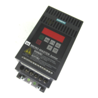
Keypad and Parameter Types:
The keypad features membrane-type keys (run, stop, up, down, P) and a 4-digit 7-segment LED display. Parameters are categorized into:
- True value parameters: Directly set values (e.g., ramp-up time P002).
- Limited range parameters: Values represent functions rather than direct quantities (e.g., P199 for access to expert parameters).
- 'Read only' parameters: Factory-set values providing information (e.g., P111 for inverter's variable torque power rating).
Accessing Parameters and Changing Values:
The up/down keys are used to change parameter values, with single presses for incremental changes and sustained presses for rapid scrolling. The display alternates between setpoint frequency and actual output frequency (0 Hz when stopped).
Parameter Ranges:
The Eco has three parameter ranges: Display mode, Basic mode, and Expert mode. P199 controls access to Expert mode.
Display Mode Parameters (DM):
P000 displays the output selected by P001 (an Expert mode parameter). Display options include output frequency (Hz), frequency setpoint (Hz), motor current (A), DC-link voltage (V), motor torque (% nominal), motor speed (rpm), USS serial bus status (Code), PID feedback signal (%), and output voltage (V). The default display is output frequency. In standby, the display flashes between setpoint and actual output frequency. Fault codes (Fnnn) are displayed during failures.
Basic Mode Parameters (BM):
- P002 Ramp-up time (0-150.0 seconds, default 20): Time for motor to accelerate from standstill to maximum frequency (P013). Too short a time can cause an F002 (overcurrent) trip.
- P003 Ramp-down time (0-150.0 seconds, default 20): Time for motor to decelerate from maximum frequency to standstill. Too short a time can cause an F001 (DC link overvoltage) trip. This also sets the period for injection braking (P073).
- P006 Frequency setpoint source selection (0-2, default 0): Selects control mode for inverter's frequency setpoint.
- 0 = Digital motorized potentiometer: Inverter runs at frequency set in P005, controlled by up/down keys. If P007=0, frequency can be increased/decreased by setting two digital inputs (P051-P055 or P356) to 11 and 12.
- 1 = Analog: Output frequency controlled by analog input signals (0-10V, 0/4-20mA, or potentiometer).
- 2 = Fixed frequency: Selected by setting at least one digital input (P051-P055 or P536) to 6 or 7.
- P007 Keypad control (0 or 1, default 1): Configures keypad control.
- 0 = Digital inputs: Control via P051-P055 or P356.
- 1 = Front panel (keypad) control enabled: Level of control determined by P121-P124.
- P012 Minimum motor frequency (0.0-150.0 Hz, default 0.00): Sets minimum motor frequency, must be less than P013.
- P013 Maximum motor frequency (0.0-150.0 Hz, default 50.00 (60.00 for North America)): Sets maximum motor frequency. Should not exceed 3x motor rating plate nominal frequency for stable operation.
- P016 Start on the fly (0 or 2, default 0): Allows inverter to start onto a spinning motor.
- 0 = Flying restart disabled.
- 2 = Flying restart enabled.
Correct motor nameplate details must be entered when enabling this feature.
- Motor Rating Plate Parameters (P081-P085): These parameters must be set using data from the motor's rating plate.
- P081 Motor rating plate nominal frequency (0-150.00 Hz, default 50.00 (60.00 for North America)).
- P082 Motor rating plate nominal speed (0-9999 RPM, default depends on inverter rating).
- P083 Motor rating plate nominal current (0.1-590.0 A, default depends on inverter rating).
- P084 Motor rating plate nominal voltage (0-1000 V, default depends on inverter rating).
- P085 Motor rating plate nominal power (0.12-400.0 kW, default depends on inverter rating).
If any of these parameters are changed from factory defaults, an auto-calibration (P088=1) should be performed. For North America operation (P101=1), P081 defaults to 60 Hz and P085 indicates hp.
- P199 Access to Expert mode (0 or 1, default 0): Enables or disables access to Expert mode parameters.
- 0 = Normal mode: Only normal mode parameters can be changed.
- 1 = Expert mode: Expert mode parameters can be changed. All parameters, including motor data (P081-P085), can be reset to factory defaults using Expert parameter P944=1.
Expert Mode - Important Parameters (EM):
Users are advised to consult the Eco Reference Manual before changing Expert parameters.
- P001 Display Mode (0-8, default 0): Same options as P000, but P010 can scale the display.
- P015 Automatic re-start after mains break (0-1, default 1):
- 0 = No re-start: Run signal must be re-generated.
- 1 = Automatic re-start: If run signal is present.
- P018 Automatic re-start after fault (0-1, default 0):
- 0 = Disabled.
- 1 = Enabled: Inverter attempts to start up to 5 times after a fault. If not cleared after 5th attempt, inverter remains in fault state.
WARNING: This means a start is pending and may happen at any time. Fault codes can be observed in P930.
- P023 Analog input 1 type (0-2, default 0): Sets analog input type in conjunction with DIP selector switches 1, 2, and 3.
- 0 = 0V to 10V/0 to 20mA Unipolar input.
- 1 = 2V to 10V/4 to 20mA Unipolar input.
- 2 = 2V to 10V/4 to 20mA Unipolar input with controlled start/stop: Motor starts when >2V.
- P027, P028, P029 Skip frequency (Hz) (0-150.0, default 0.0): Set skip frequencies to avoid mechanical resonance. Frequencies within +/-2Hz (P019) of these settings are suppressed, preventing stationary operation in these ranges.
- P051-P055, P356 Selection control function for digital inputs (0-24, defaults vary): Configure digital input functions. Fixed frequency is enabled when these are set to 6 or 18, and P006 should be set to 2.
- Value 0: Input disabled.
- Value 1: ON right.
- Value 4: OFF2.
- Value 5: OFF3.
- Value 6: Fixed frequencies 1-6.
- Value 9: Start/stop command selection from keypad OR digital terminals.
- Value 10: Fault reset.
- Value 11: Increase frequency.
- Value 12: Decrease frequency.
- Value 13: Switch between analog input frequency setting and digital/keypad frequency setting.
- Value 14: Disable ability to change parameters.
- Value 18: Fixed frequencies 1-6, but input high will also request RUN when P007=0.
- Value 19: External trip.
- Value 22: Download parameter set 0 from OPe.
- Value 23: Download parameter set 1 from OPe.
- Value 24: Switch analog setpoint.
- P061, P062 Selection relay output RL1/RL2 (0-13, defaults 6 and 1): Sets the function for relay outputs.
- Value 0: No function assigned (relay not active).
- Value 1: Inverter is running (High).
- Value 2: Inverter frequency 0.0 Hz (Low).
- Value 5: Inverter frequency less than or equal to minimum frequency (Low).
- Value 6: Fault indication (Low).
- Value 7: Inverter frequency greater than or equal to setpoint (High).
- Value 9: Output current greater than or equal to P065 (High).
- Value 12: PID closed loop motor LOW speed limit (High).
- Value 13: PID closed loop motor HIGH speed limit (High).
'Active low' means relay OFF/de-energized; 'Active high' means relay ON/energized.
- P073 DC injection braking (%) (0-200, default 0): Rapidly stops the motor by applying a DC braking current, holding the shaft stationary for the duration set by P003. This generates additional heat. DC brake can be activated using DIN 1 to DIN 6 (P051-P055, P356).
WARNING: Frequent use of long periods of DC injection braking can cause motor overheating. If enabled via a digital input, DC current is applied as long as the digital input is high, causing motor heating.
- P076 Pulse frequency (0-7, default 0): Sets the pulse frequency (2 to 16 kHz) and PWM mode. Lower frequencies reduce inverter losses and RFI emissions if silent operation is not critical.
- 0/1 = 16 kHz.
- 2/3 = 8 kHz.
- 4/5 = 4 kHz (400V default).
- 6/7 = 2 kHz.
Even numbers use normal modulation, odd numbers use lower loss modulation for speeds above 5 Hz. Note: 8KHz or 16KHz may reduce output current rating.
- P086 Motor current limit (%) (0-200, default 100): Defines motor overload current as a percentage of nominal motor current (P083) allowed for up to one minute. This limits motor current and prevents overheating. If exceeded for one minute, output frequency is reduced until current falls to P083. The inverter can trip using the relay in conjunction with P074. Maximum value is limited by inverter rating.
Fault Codes:
The manual provides a list of fault codes (F001-F231) with their causes and corrective actions, such as overvoltage, overcurrent, overload, overheating, USS protocol time-out, initialization fault, internal interface fault, external trip, program fault, start on fly, motor overtemperature, parameter faults, digital input parameter faults, automatic calibration failure, and output current measurement imbalance. Corrective actions typically involve checking supply voltage, ramp times, motor connections, motor parameters, ambient temperature, serial interface settings, or resetting parameters.