EasyManua.ls Logo

Siemens MICROMASTER User Manual

Siemens MICROMASTER
42 pages
To Next Page IconTo Next Page
Page #1 background imageLoading...
Page #1 background image
© Siemens plc 1997
G85139-H1750-U049-B
26/09/97
Contents
Safety Instructions ..............................................................2
1. OVERVIEW ......................................................................3
2. INSTALLATION ...............................................................4
3. FRONT PANEL CONTROLS & BASIC OPERATION ...14
4. OPERATING MODES ....................................................17
5. SYSTEM PARAMETERS...............................................20
6. FAULT CODES ..............................................................34
7. SPECIFICATIONS..........................................................35
8. SUPPLEMENTARY INFORMATION .............................37
MICROMASTER
Operating Instructions
Question and Answer IconNeed help?

Do you have a question about the Siemens MICROMASTER and is the answer not in the manual?

Siemens MICROMASTER Specifications

General IconGeneral
BrandSiemens
ModelMICROMASTER
CategoryDC Drives
LanguageEnglish

Summary

Safety Instructions

European Low Voltage Directive

Describes compliance with the Low Voltage Directive 73/23/EEC.

European Machinery Directive

Discusses compliance with essential Health & Safety requirements.

European EMC Directive

Details compliance with the EMC Directive for Power Drive Systems.

ISO 9001

Siemens plc operates a quality management system compliant with ISO 9001.

1. OVERVIEW

Overview

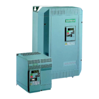
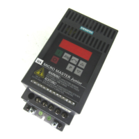
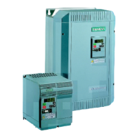
The MICROMASTERS are frequency inverters for controlling the speed of three phase AC motors.

2. INSTALLATION

2.1 Wiring Guidelines to Minimise the Effects of EMI

Guidelines to minimize Electro-Magnetic Interference (EMI) during installation.

2.2 Mechanical Installation

Covers environmental requirements and ideal installation practices for the inverter.

2.3.1 Power and Motor Connections - Frame Size A

Details power and motor connections for Frame Size A inverters.

2.3.2 Power and Motor Connections - Frame Size B

Explains power and motor connections for Frame Size B inverters.

2.3.3 Power and Motor Connections - Frame Size C

Details power and motor connections for Frame Size C inverters.

2.3.4 Control Connections

Explains how to make control connections to the inverter terminals.

2.3.5 Motor Overload Protection

Discusses motor overload protection using PTC sensors and parameter settings.

2.3.6 Block Diagram

Provides a block diagram illustrating the inverter's internal structure and connections.

3. FRONT PANEL CONTROLS & BASIC OPERATION

3.1 Front Panel Controls

Details the functions of the buttons and the LED display on the inverter's front panel.

3.2 Basic Operation

Covers general operation, initial testing, and a 10-step guide for basic setup.

4. OPERATING MODES

4.1 Digital Control

Describes basic startup configuration using digital control.

4.2 Analogue Control

Details basic startup configuration using analogue voltage control.

4.3 Stopping the Motor

Explains different methods for stopping the motor, including ramp down, coasting, and braking.

4.4 If the Motor Does Not Start Up

Provides troubleshooting steps for when the motor fails to start.

4.5 Local and Remote Control

Describes how to control the inverter locally via the panel or remotely via RS485.

4.6 Closed Loop Control

Explains PI control function, hardware setup, and parameter settings for closed loop operation.

5. SYSTEM PARAMETERS

6. FAULT CODES

7. SPECIFICATIONS

8. SUPPLEMENTARY INFORMATION

8.1 Application Example

Demonstrates a setup procedure for a simple application using the inverter.

8.2 USS Status Codes

Explains the meaning of status codes displayed during serial link communication.

8.3 Electro-Magnetic Compatibility (EMC)

Details EMC performance characteristics across three classes for different environments.

8.4 Environmental Aspects

Covers transport, storage, dismantling, disposal, and documentation aspects of the inverter.

8.5 User's Parameter Settings

A table to record user-specific parameter settings with default values.

Related product manuals