EasyManuals Logo

Siemens MICROMASTER User Manual

Siemens MICROMASTER
42 pages
To Next Page IconTo Next Page
To Previous Page IconTo Previous Page
Page #13 background imageLoading...
Page #13 background image
2. INSTALLATION English
© Siemens plc 1997 G85139-H1750-U049-B
13
2
6/09/9
7
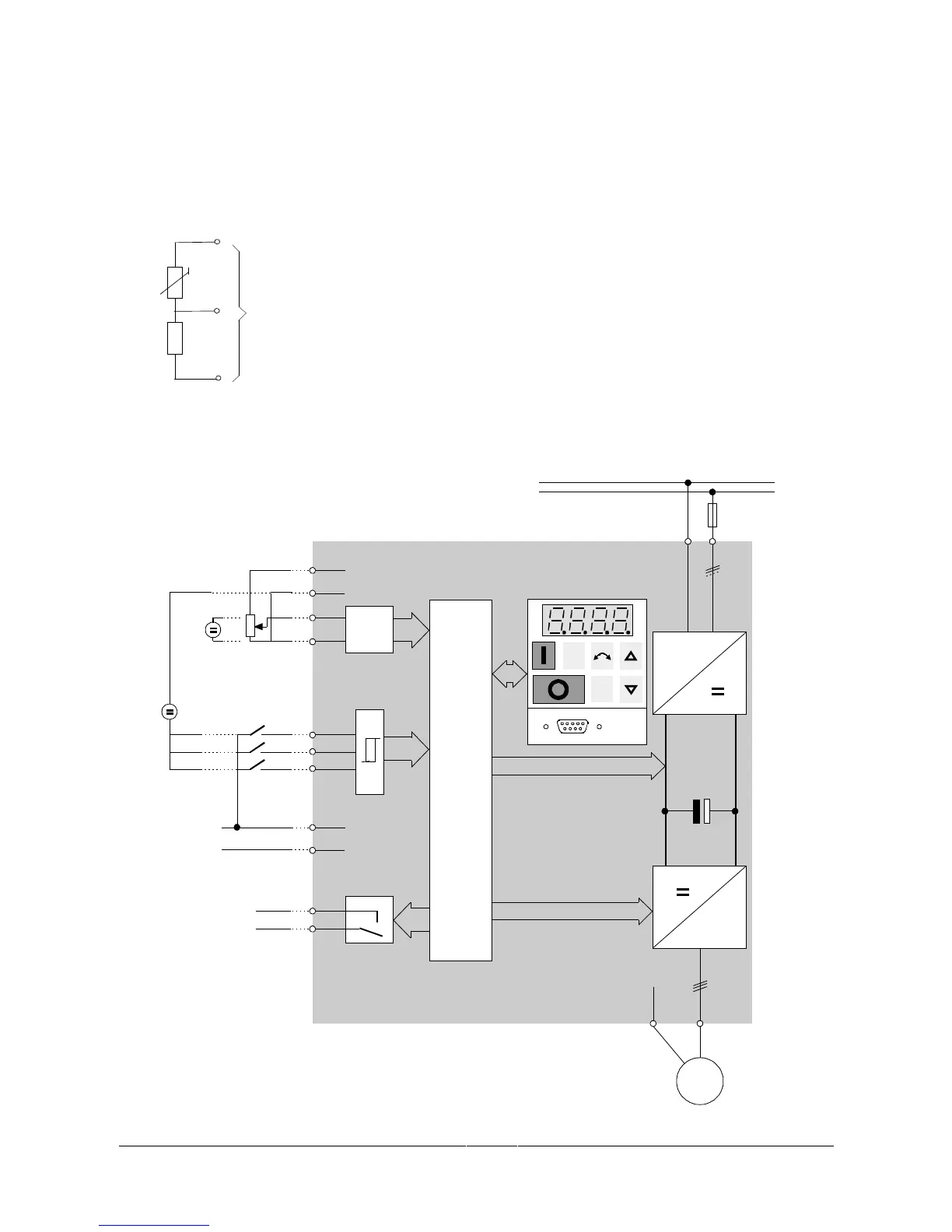
2.3.5 Motor Overload Protection
When operated below rated speed, the cooling effect of fans fitted to the motor shaft is reduced.
Consequentially, most motors require de-rating for continuous operation at low frequencies. To ensure that
motors are protected against overheating under these conditions, a PTC temperature sensor must be fitted to
the motor and connected to the inverter control terminals as shown in Figure 7.
Note: To enable the trip function, set parameter P051, P052 or P053 =19.
MOTOR
P
T
C
1k
8
9
7
Inverter Control
Terminals
Figure 7: Motor Overload PTC Connection
2.3.6 Block Diagram
P
Jog
M
PE U, V, W
3 ~
CPU
AD
SI
2
3
4
5
6
10
11
PE
1/3 AC 230 V
3 AC 380 - 500 V
L/L1, N/L2
or
L/L1, N/L2, L3
1
7
+10V
0V
+
24 V
OR
OR
V:
0 - 10 V
2 - 10 V
AIN+
AIN-
DIN1
DIN2
DIN3
PE
RL1
4.7 k
~
RL1B
RL1C
8
+15V
0V
9
Power Supply for
PI Feedback
Transducer
or other load.
RS485
Figure 8: Block Diagram

Questions and Answers:

Question and Answer IconNeed help?

Do you have a question about the Siemens MICROMASTER and is the answer not in the manual?

Siemens MICROMASTER Specifications

General IconGeneral
BrandSiemens
ModelMICROMASTER
CategoryDC Drives
LanguageEnglish

Related product manuals