EG
8
APPLICATION EXAMPLES..............................................
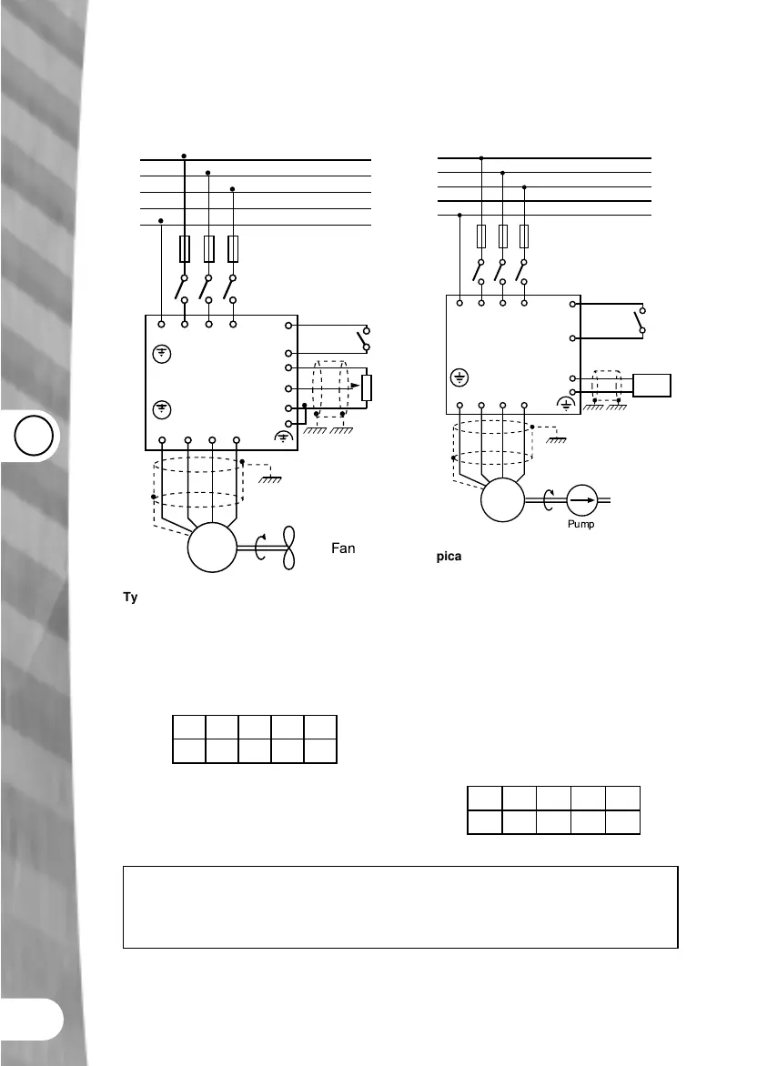
FAN CONNECTION
L1 L2 L3PE
UVWPE
L1
L2
L3
N
PE
F1
Eco
B
A
9
5
1
3
2
4
M
3 ~
Fan
Typical fan connection
To speed control a fan between 0-50 Hz, (60
Hz in North America) a potentiometer is used
or 0-10V speed setting signal.
DIP Switch Configuration
•
•
• •
•
PUMP CONNECTION
L1 L2 L3PE
UVWPE
L1
L2
L3
N
PE
F1
Eco
M
3 ~
A
C
9
5
3
4
0-20mA
Pump
Typical pump connection
To control the speed of the pump in a pumping
system a 0-20 mA control signal is used; this
corresponds to a 0-100% motor speed -
normally 0-50 Hz (60 Hz in North America).
A signal representing the output frequency is
required, i.e. as an indication of the motor
speed. An analog output (terminals 12 & 13)
of 0-20 mA is used, which corresponds to a
frequency of 0-50 Hz (60 Hz in North America).
DIP Switch Configuration
•
•
• •
•
P006=1, P007=0 (Basic mode Parameter changes from factory default)
A External switch or relay, contact
B Potentiometer or 0-10 V signal
C Speed control signal