7
ELECTRICAL INSTALLATION.........................................
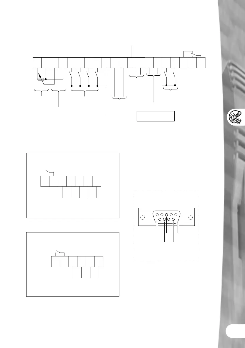
Output Relays (RL1 and RL2)
max. 0.8 A/230V AC
(Overvoltage cat.2)
2.0 A/30 V DC
(resistive rating)
21 22 23 24 25 26 27
RL2B
(NO)
RL2C
(COM)
P5V+ N-N- P+ PE
Analog Output 2
0/4 ....20 mA
(500Ω load)
use with terminal 13
RS485
(for USS protocol)
MIDIMASTER Eco
RANGE
A2OUT+
Front Panel
RS485 D-type
5
9
1
6
OV P+
PE (case)
N-
5V (max. 250mA)
1 2 3 4 5 6 7 8 9 10 11 12 13 14 15 16 17 18 2019
P10+ 0V AIN+ AIN- DIN1 DIN2 DIN3
DIN4
P15+ PIDIN+ PIDIN- AOUT- PTC PTC DIN5 DIN6
Power Supply
(+10 V, max. 10mA)
Analog Input 1
-10 V to +10 V
0/2 .... 10V
(input impedance 70kΩ)
or
0/4 .... 20mA
(Resistance = 300Ω)
Digital Inputs
(7.5....33 V, max. 5mA)
Power Supply
for PID Feedback
Transducer
(+15V, max. 50mA)
Analog input2
0 .... 10 V
or
0 .... 20mA
Micromaster
Analog Output
Midimaster
Analog Output 1
0/4....20 mA
(500Ω load)
Motor temp.
protection input
Note: For PTC motor thermal
protection, P087 = 1
Digital Inputs
(7.5 ....33 V, max 5mA)
RL1A
(NC)
RL1B
(NO)
RL1C
(COM)
Output Relays (RL1 and RL2)
max. 0.8 A/230V AC
(Overvoltage cat.2)
2.0 A / 30 V DC
(resistive rating)
21 22 23 24 25 26
RL2B
(NO)
RL2C
(COM)
P5V+N-N- P+PE
RS485
(for USS protocol)
MICROMASTER Eco
RANGE
MIDIMASTER A1 OUT+
MICROMASTER A OUT+
Analog Input 1–10 V to+10 V
0/2… 10V
(Input impedance 70kΩ)
or
0/4….20mA
(Resistance = 300Ω)