Siemens Industry, Inc.
Building Technologies Division
P/N 315-033240-1312
Figure 13
CAN Wiring - Remote Enclosure Without An RNI
+24 V
CAN +
CAN –
SHIELD
SHIELD (OPTIONAL)
24V RETURN
PSC-12
RESET
POWER
MODULE FAIL
H - NET FAIL
GND FAULT
24V 12 FAIL
24V 4A FAIL
CAN FAIL
TB3
CAN +
–
+
_
P4
TB1
P5
BATTERY
AC
TB2
1
++
__
2
HNGND
P9
P12
TB4
1
2
3
4
5
6
7
8
9
0
1
2
3
4
5
6
7
8
9
0
1
2
3
4
5
6
7
8
9
0
1
2
3
4
5
6
7
8
9
0
1
2
3
4
5
6
7
8
9
0
1
2
3
4
5
6
7
8
9
0
FCM-6
LCM-8
OR
SCM-8
LCM-8
OR
SCM-8
P1
P2
10 11 12
CAN TERMINATOR
P/N 110-134215
INCLUDED IN CAN TERMINATOR KIT
(SHIPPED WITH THE NIC-C)
*
*
1 2 3 4 5 6 7 81 2 3 4 5 6 7 81 2 3 4 5 6 7 8
9 10 11 12 13 14 1 5 169 10 11 12 13 14 15 169 10 11 12 13 14 15 16
17 18 19 20 21 22 23 2417 18 19 20 21 22 23 2417 18 19 20 21 22 23 24
1
2
3
4
5
6
7
8
9
0
1
2
3
4
5
6
7
8
9
0
1
2
3
4
5
6
7
8
9
0
1
2
3
4
5
6
7
8
9
0
1
2
3
4
5
6
7
8
9
0
1
2
3
4
5
6
7
8
9
0
S1
1
5
3
7
2
6
4
8
S2
1
5
3
7
2
6
4
8
S1
1
5
3
7
2
6
4
8
S2
1
5
3
7
2
6
4
8
S1
1
5
3
7
2
6
4
8
S2
1
5
3
7
2
6
4
8
OCM-16OCM-16OCM-16
1 2 3 4 5 6 7 8
1 2 3 4 5 6 7 8
9 10 11 12 13 14 15 16
9 10 11 12 13 14 15 16
1
2
3
4
5
6
7
8
9
0
1
2
3
4
5
6
7
8
9
0
TB2
TB1
P2 P3
TB3
TB4
SIM-16
REFER TO
SINGLE
ENCLOSURE
WIRING
DIAGRAM
FIG. 6
CLASS-B/
STYLE 4
(ULC DCLB)
NOTES:
1. 18 AWG min., 12 AWG max.
2. 15 ohms max. for CAN
network.
3. Use twisted pair or twisted
shielded pair.
4. Power limited to NFPA 70
per NEC 760.
5. All field wiring supervised.
The screw terminals can accommodate one 12 -18 AWG or two 16-18 AWG.
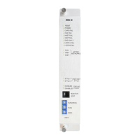
INSTALLATION The NIC-C plugs perpendicularly into one slot in the CC-5 card-cage via two 96-pin
DIN connectors and can occupy any slot in the card cage. (Refer to Figure 14.)
Insert the NIC-C card into the card guides rightside up (lettering on the
front panel is legible)
Slide the card in until the card edge connectors contact the recep-
tacles on the motherboard.
Verify that the DIN connectors of the card and the card-cage aligned
properly. The card can only plug in one direction to the card cage, if it
does not align, DO NOT FORCE the card.
Place thumbs on the front panel adjacent to the captive screws and
gently apply even pressure on the card until the connectors seat in the
receptacles on the motherboard. Secure with the captive screws.
Figure 14
Installing The NIC-C
rewoPtupnI rewoPtuptuO
tnerruCenalPkcaBV42Am021
TENX/TENHhcaE
riaPkrowteNNACdnA
.xamkaepotkaepV8
tnerruCV42l
animreTwercS0 )noissimsnartgsmgnirud(.xamAm57
tnerruCenalPkcaBV2.60
tnerruCybdnatSV42Am021
ELECTRICAL RATINGS
 Loading...
