Siemens Industry, Inc.
Building Technologies Division
P/N 315-033240-132
The NIC-C supervises each network to insure proper operation. Any faults that are
detected by the NIC-C are reported to the PMI/PMI-2/PMI-3 (XLS), FCM2041-U2
(Desigo Fire Safety Modular), FCM2041-U3 (Cerberus PRO Modular) for annunciation.
In addition, the NIC-C has diagnostic LEDs that indicate which faults have been
found. Individual LEDs are included for HNET/XNET Loop A and Loop B faults, as well
as an LED for complete failure of the HNET or XNET network or the CAN network.
The NIC-C can also be configured to perform ground fault detection on both net-
works.
Features The NIC-C isolates short circuit faults to each individual segment of the HNET/XNET
network. If a short occurs, only the segment of wire between the two NIC-Cs is
affected. In a Class-B/Style 4 system the network will be divided into two sections.
Communication in each of the sections will continue. For a Class-X/Style 7 network,
the fault will be detected and the network will continue to operate as a single
network. An HNET/XNET network monitoring jack is included for connection of
diagnostic tools. This jack is located on the front bezel.
The NIC-C supports the LCM-8/SCM-8/FCM-6/OCM-16/SIM-16 CAN modules. LEDs
are visible through the front bezel to indicate the NIC-C configuration. All switch
selectable options are displayed here. This allows for easy confirmation of the NIC-C
configuration settings.
The NIC-C is compatible with the XNET Bridge. Refer to the XNET Bridge installation
instructions, P/N 315-050017, for more details.
TENHTENX
4elytS/B-ssalC7elytS/X-ssalC4elytS/B-ssalC7elytS/X-ssalC
,)SLX(3-IMP/2-IMP/IMP
eriFogiseD(2U-1402MC
F
,)raludoMytefaS
surebreC(3U-1402MCF
)TENH()raludoMORP
YY * *
3-IMP/2-IMP/IMPlabolG
2U-1402MCF,)SLX(
ytefaSeriFo
giseD(
3U-1402MCF,)raludoM
)raludoMORPsurebreC(
)TENX(
**Y **N
MER-DSS/C-DSS/DSS
LTNI-C-DSS/LTNI-DSS
YN* *
MPRYN**
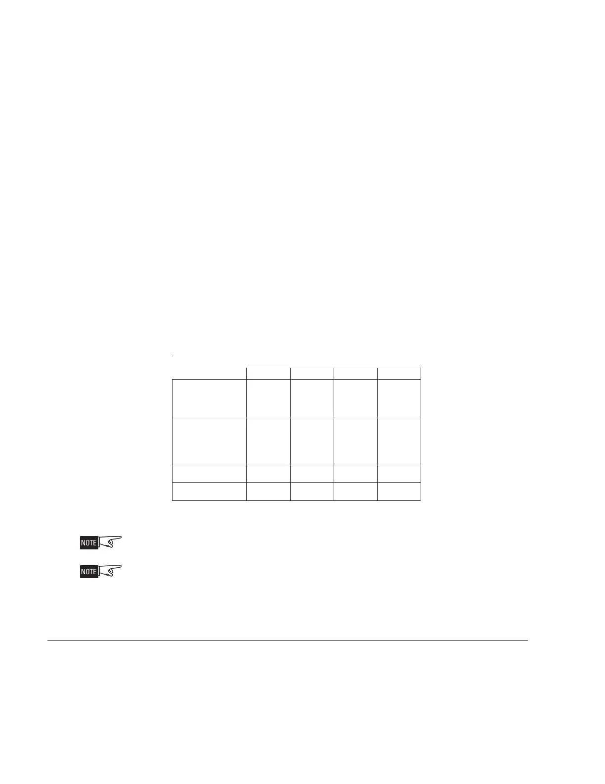
dewollA
toN=N,dewollA=Y
.krowtensihtnodewollatoN*
.seYesiwrehto,4XOBMER/2XOBMERanidellatsninehW**
Class-B/Style 4 = ULC DCLB
Class-X/Style 7 = ULC DCLC
In Canada, ULC S524 requires that all interconnecting data communications links for
networks be wired DCLC (style 7) except for dedicated network communication to
annunciators.
Table 1
Module Placement At The End Of a HNET Or XNET Network
OPERATION Network supervision is accomplished through passive monitoring of the network
signals. No additional bandwidth is required. Each NIC-C continuously monitors all
networks for activity and reports any problems to the PMI/PMI-2/PMI-3 (XLS),
FCM2041-U2 (Desigo Fire Safety Modular), FCM2041-U3 (Cerberus PRO Modular). In
some cases, a reset at the PMI/PMI-2/PMI-3 (XLS), FCM2041-U2 (Desigo Fire Safety
Modular), FCM2041-U3 (Cerberus PRO Modular) is required to clear network troubles.