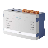
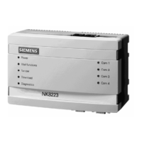
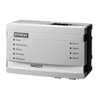
NK823x Structure and Functions
24
Building Technologies
048_DMS_NK8000_ICC_MP4.40_A6V10062437_a_en.doc
Fire Safety & Security Products 06.2011
The four LED's on the right side are, from top to bottom:
Front panel LED (right Functions
Com1 Status Com1
Com2 Status Com2
Com3 Status Com3
Com4 Status Com4
Red: RX
Green: TX
Tab.6. LED functions on the front panel, right side
5.2 Internal DIP switches
The internal DIP switches (S101) enable a download session via FTP using a de-
fault IP address.
Internal switch Functions
DIP switch 1 Default mode/network access:
If DIP-switch 1 is ON, an FTP connection occurs by default on the
Ethernet 1 at the default IP address 192.168.9.41.
DIP switch 2 Default mode/network access:
If DIP-switch 2 is ON, an FTP connection occurs by default on the
Ethernet 2 at the default IP address 192.168.10.41.
Tab.7. Internal DIP switches
5.3 Internal jumpers
The internal jumpers (see Fig. 8) are used for:
X115: When closed, it disables the box tamper alarm.
Fig. 8 NK823x internal DIP switch and jumpers (NKM8001-A2 mainboard)
X104
X3
X103
S101: DIP-Switches
S2: Tamper switch
S1: Reset button
X2
X1
X101
X102
X111
X105

 Loading...


