EasyManua.ls Logo

Siemens OOHC941

Siemens OOHC941
8 pages
To Next Page IconTo Next Page
Loading...
A6V10324661_en--_m
SIEMENS Industry, Inc.
2020-08-28
Smart Infrastructure
Installation Instructions
Model OOHC941
Multi-Criteria Fire/CO Detector
UL268 7th edition listed
Figure 1
These instructions are written in accordance with the
installation guidelines of NFPA 72, National Fire Alarm
Code and CAN/ULC-S524, The Installation of Fire
Alarm Systems
. The model OOHC941 detector (as
shown in Figure 1) meets the VEWFD (Very Early
Warning Fire Detector) classification and sensitivity
requirements of NFPA 76 (Standard for the Fire
Protection of
Telecommunications Facilities)
incorporating a programmable “Alert” (Pre-
Alarm)
sensitivity threshold of 0.2%/ft obscuration and an
“Alarm” sensitivity threshold of 1.0%/ft obscuration.
CAUTION
DO NOT install this detection device until all
construction
is completed.
DO NOT store this detection device where it can be
contaminated by dirt, dust, or humidity.
DETECTOR PLACEMENT
Although no specific spacings are set for the detectors
used for a clean air application, for multi-
criteria fire
detection use 30-foot
center spacing (900 sq ft) from
NFPA 72 initiating devices chapter, if practical, as a
guide or starting point for a detector installation layout.
This spacing, however, is based on ideal conditions
smooth ceiling, no air movement, and no
obstructions. In some applications, therefore,
considerably less area is protected adequately by each
smoke detector. This is why it is mandatory to closely
follow the installation drawings. In all installations place
the detector on the ceiling,
a minimum of 6 inches from
a side wall, or on a wall,
12 inches from the ceiling. For
CO gas detection applications, follow detector
installation requirements in NFPA 72
for Installation of
Carbon Monoxide Detection and Warning Equipment.
For thermal detection, use the matrix below:
Spacing, Feet Temperature Rating, °F With/without Guard Model
50
135, 145, 155, 165, 175
With and without STI Guard
60 135, 145, 155, 165, 175
70 135, 145
Drawings provided or approved by Siemens
Industry,
Inc., or by its authorized distributors are
extremely
important.
The detector placements shown on these
drawings were chosen after a careful evaluation of the
area that is protected. Such factors as air currents,
temperature, humidity, pressure,
and the nature of the
fire load were carefully considered. Especially noted
were the room or area configuration and the type of
ceiling (sloped or flat, smooth or beamed). Siemens
Industry, Inc.’s extensive experience in the design of the
system assures th
e best detector placement by following
these drawings.
Sound engineering judgment by
qualified personnel must be followed.
TO AVOID NUISANCE ALARMS
Do not locate the detectors where excessive smoke
concentrations exist under normal conditions, or in areas
of prolonged high relative humidity where condensation
occurs.
Do not locate the detectors next to an oil burner,
or
garage where exhaust fumes can trigger an alarm. Other
causes of false alarm are dust accumulation, heavy
concentrations of steam,
heavy pipe or cigar smoke, and
certain aerosol sprays.
Question and Answer IconNeed help?

Do you have a question about the Siemens OOHC941 and is the answer not in the manual?

Siemens OOHC941 Specifications

General IconGeneral
BrandSiemens
ModelOOHC941
CategoryGas Detectors
LanguageEnglish

Summary

Installation Instructions

Detector Placement

Guidance on selecting optimal locations for detector installation, considering various factors.

Nuisance Alarm Avoidance

Recommendations to prevent false alarms by avoiding specific environmental conditions.

Detector Installation Factors

Air Currents and Smoke Travel

Explains how air movement affects smoke detection and detector placement.

Ceiling Construction Impact

Discusses how ceiling obstructions affect air and smoke movement for detection.

Environmental Conditions

Details temperature, humidity, pressure, and air velocity ranges for detector operation.

LED Indicator Status

Describes the meaning of different LED color flashes and their operational states.

Detector Programming

Covers detector addressing, parameter sets, and channel configurations for optimal performance.

Detector Configuration and Electrical

Selectable Thresholds

Lists selectable fixed temperature and alarm threshold setting profiles for the detector.

Electrical Specifications

Provides details on supply voltage, maximum alarm, and standby current.

Wiring Modes

Explains polarity insensitive and isolator wiring modes for detector installation.

Isolator Mode Notice

Critical notice regarding isolator mode compatibility with product version 30.

Application Profiles

Selectable Application Profiles

Details various selectable application profiles for different environmental conditions.

CO Life Safety Profile

Describes the Balanced US1 CO Life Safety Profile and its compliance standards.

Testing and Wiring Diagrams

Detector Testing Procedures

Outlines procedures for functional and sensitivity testing by qualified personnel.

Polarity Insensitive Wiring

Illustrates the wiring diagram for the polarity insensitive mode of the detector.

Isolator Mode Wiring

Illustrates the wiring diagram for the isolator mode of the detector.

Wire Size Recommendation

Specifies the recommended wire gauge for connecting the detector to prevent damage.

Detector Mounting and Testing

Wall Mounting and Guard Orientation

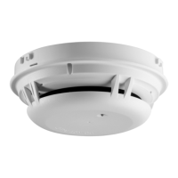
Provides instructions for correct detector wall mounting and guard positioning.

Smoke Detector Functional Test

Details the procedure for performing a functional smoke entry test with approved gases.

CO Detector Functional Test

Details the procedure for performing a functional CO gas entry test with approved gases.

Maintenance and System Replacement

Detector Maintenance and Handling

Covers routine maintenance, sensitivity indication, and cautions against disassembly or painting.

Detector Replacement in Existing Systems

Instructions for replacing older detectors, noting differences in alarm verification features.

Special Application Profile Usage

Guidelines for using the Telecommunications application profile and unsuitable environments.

FCC Statement

Warning on RF Interference

Alerts users about potential radio frequency interference from improper installation or usage.

Related product manuals