EasyManua.ls Logo

Siemens Water Technologies Series - User Manual

Siemens Water Technologies Series
55 pages
Print Icon
To Next Page IconTo Next Page
Loading...
ACUTEC 35
GAS DETECTION
SYSTEM
BOOK NO. WT.050.130.000.UA.IM.1108

Questions and Answers

  • A
    andersenalexandraJul 28, 2025
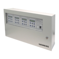
    What to do if Siemens Gas Detectors receiver module does not respond to test gas?
    • K
      Kenneth RogersJul 28, 2025
      If the Siemens Gas Detectors receiver module powers up correctly but doesn't respond when test gas is applied, first disconnect the transmitter connections at the two “TR” terminals of the receiver and check the voltage with a voltmeter. It should be approximately 12 Vdc. Next, connect a milliamp meter between the two “TR” terminals of the receiver; the current should be 15 to 25 mA.
  • Y
    yrobinsonAug 12, 2025
    How to troubleshoot Siemens Water Technologies when receiver LEDs do not light?
    • X
      xhayesAug 12, 2025
      If the receiver LEDs and indicators of your Siemens Gas Detectors do not light up when power is applied, start by checking the fuse and replace it if blown. If the fuse is intact, inspect the wiring from the Power Supply Module to the Receiver Module, ensuring correct polarity. Then, use a voltmeter to check the power supply at the “+12” and “C” terminals on the Receiver; if the reading is between 13.6 to 13.9 Vdc, the Receiver should be replaced. Also, measure the AC input voltage at the Power Supply Module. If it's outside the rated range (see Section 1.1 - Technical Data), check the AC supply. Finally, if the voltage measured in step 3 exceeds 13.9 V, connect another Receiver Module or a resistive load of approximately 100 ohm and 2 watts to the Power Supply output terminals.

Summary

Product Information and Warranty

Ordering Information

How to order system components and parts by description and part number.

Warranty Policy

Details of the product warranty, including terms and limitations.

System Introduction and Safety Guidelines

Acutec 35 System Overview

General description of the Acutec 35 gas detection system and its purpose.

Critical Safety Precautions

Essential safety rules for installation, operation, and maintenance to prevent injury.

Technical Data and Support Contacts

System Technical Specifications

Performance data, gas ranges, operating conditions, and power requirements.

Regional Support Offices

Contact information for Siemens Water Technologies service locations in the US and Canada.

Installation and Wiring Procedures

General Installation and Mounting

Guidelines for mounting enclosures and making conduit connections.

Electrical Connections and Wiring

Instructions for connecting power, receiver, and transmitter modules.

Installation Wiring Diagrams

Schematics detailing system wiring for single and dual point configurations.

System Operation and Configuration

Receiver Module Configuration

Setting system parameters like range and setpoints via DIP switches.

Operation Modes and Functions

Features including auto-test, alarm acknowledge, relay inhibit, and manual testing.

Sensor and Battery Backup Operation

Functionality of sensors, transmitters, and the battery backup system.

Service, Maintenance, and Troubleshooting

Sensor Service and Calibration

Procedures for sensor response testing, replacement, and calibration.

Routine Maintenance and Troubleshooting

Scheduled service tasks and solutions for common system issues.

Illustrations and Parts

System Component Illustrations

Visual guides for system parts, assemblies, and diagrams.

Spare Parts List

Catalog of available replacement parts and their corresponding part numbers.

Siemens Water Technologies Series Specifications

General IconGeneral
TechnologyElectrochemical
Output4-20 mA
Power Supply24 VDC
Operating Temperature-20°C to +50°C (varies by model)
Enclosurepolycarbonate
Protection RatingIP65
CertificationsUL, CSA

Related product manuals