24/44
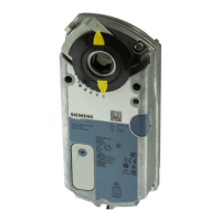
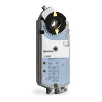
Siemens Rotary actuators without spring return GBB/GIB..1 CE1Z4626en
Smart Infrastructure Wiring notes 2019-11-28
The following sections show how to determine the permissible line length and cross-
sectional areas for the various actuators based on examples.
The examples for actuators connected in parallel apply to the following arrangement:
L1
L2 A1
L2
L2
A2
L2 A3
A4
L1
G0
G0
G0
G0
G0
G0
G
G
G
G
G
G
Controller
4614S01en
The line resistances of L2 are equal and can be ignored for L1. Separately calculate the
permissible line lengths L2 for other connections (ring, star-like).
6.2 Actuator wiring (three-position)
With three-position actuators, only the situation as presented under AC 24 V is
important. Sizing takes place via lines 1 (G), 6 (Y1), and 7 (Y2).
The table shows the power consumption of an actuator as well as the permissible
voltage drop.
Operating
voltage/pos. signal
Power
consumption
Perm. voltage drop for line
1 (G), 6 (Y1), 7 (Y2)
AC 24 V 7 VA
DU/U = max. 8 % (4 % each per line)
The diagram shows the currents in the connecting lines for one actuator.
4626G04en
M
AC 24 V AC 0.29 A
G
Y1
Y2
GBB13...
1
7
6
Open
0 V
Determining the line lengths for two actuators GBB/GIB13..1 and AC 24 V supply.
Only the currents in line 1 (G) and 6 (Y1) or 7 (Y2) determine the line sizing.
Max. permissible voltage drop = 4 % per line (total 8 %).
· Consumption = 2 x 7 VA = 14 VA
· Line current = 2 x 0.29 A = 0.58 A
Max. permissible single line length: 140 m at 1.5 mm
2
cross-sectional area.
Line length for actuators
Actuators with three-
position control
Power consumption and
perm. voltage drop with
P&I diagram:
Example:
Parallel connection
 Loading...