OpenAir® GDE Enhanced Non-Spring Return Rotary Electric Damper Actuator Technical Instructions
Document Number 155-784
October 20, 2016
Siemens Industry, Inc. Page 11
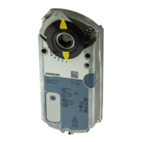
To move the damper blades and lock the position with no
power present:
1. Slide the red manual override knob toward the back of
the actuator.
2. Make adjustments to the damper position.
3. Slide the red manual override knob toward the front of
the actuator.
Once power is restored, the actuator returns to automated
control.
Figure 19.
Manual Override.
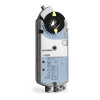
Mechanical
Range
Adjustment
To mechanically limit the range of the damper blade, do the following:
1. Loosen the stop set screw.
2. Move the screw along the track to
the desired position, and fasten it
in place.
Figure 20. Moving the Mechanical Range Stop.
To use the entire 0(2) to 10V input signal to control the mechanically limited range,
see Figure 17 for setting self-adaptive features.
Stop set screw at 70°
Self-adapt switch ON
Input signal Y = 5 Vdc
The damper will be at 35° (50% of the adjusted range.)
NOTE: On versions with the slope and offset features, this example assumes
Offset Uo = 0 Vdc
Slope U = 10 Vdc
All wiring must conform to NEC and local codes and regulations.
Use earth ground isolating step-down Class 2 transformers. Do not use autotransformers.
The sum of the VA ratings of all actuators and all other components powered by one
transformer must not exceed the rating of the transformer.
It is recommended that one transformer power no more than 10 actuators.
WARNING:
All six outputs of the dual auxiliary switch (A and B) must only be connected to:
Class 2 voltage (UL/CSA).
Separated Extra-Low Voltage (SELV) or Protective Extra Low Voltage
(PELV) (according to HD384-4-41) for installations requiring conformance.

 Loading...