Technical Instructions OpenAir® GDE Enhanced Non-Spring Return Rotary Electronic Damper Actuator
Document Number 155-784
October 20, 2016
Page 12 Siemens Industry, Inc.
WARNINGS:
Installations requiring Conformance:
All wiring for CE certified actuators must be SELV or PELV rated per
HD384-4-41.
Use safety-isolating transformers (Class III transformer) per EN61558.
They must be rated for 100% duty cycle.
Over current protection for supply lines is maximum 10A.
Each wire has the standard symbol printed on it. See
Table 4.
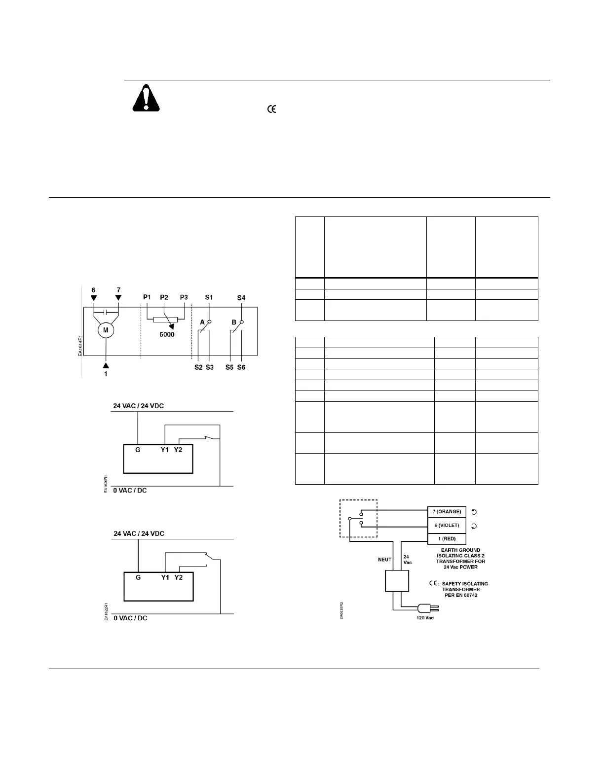
GDE14x
24 Vac/dc Power Supply, 2-Position/Floating
Control
Figure 21. GDE14x Wiring Diagram.
Figure 22. 2-Position, SPST
(Single-Pole, Single-Throw).
Figure 23. 2-Position, SPDT
(Single-Pole, Double-Throw).
Table 4. 2-Position/Floating Control 24 Vac/dc.
Control signal
counterclockwise
Factory-installed Options
Feedback Potentiometer
0 to 100% P1 - P2
(0 to 5,000 ohms)
Feedback Potentiometer
Common
Feedback Potentiometer
100 to 0% P3 - P2
(5,000 to 0 ohms)
Figure 24. Floating Control
24 Vac/dc.

 Loading...