Technical Instructions OpenAir® GDE Enhanced Non-Spring Return Rotary Electronic Damper Actuator
Document Number 155-784
October 20, 2016
Page 8 Siemens Industry, Inc.
GDE146.1P, GDE346.1U, GDE164.1P, GDE166.1P
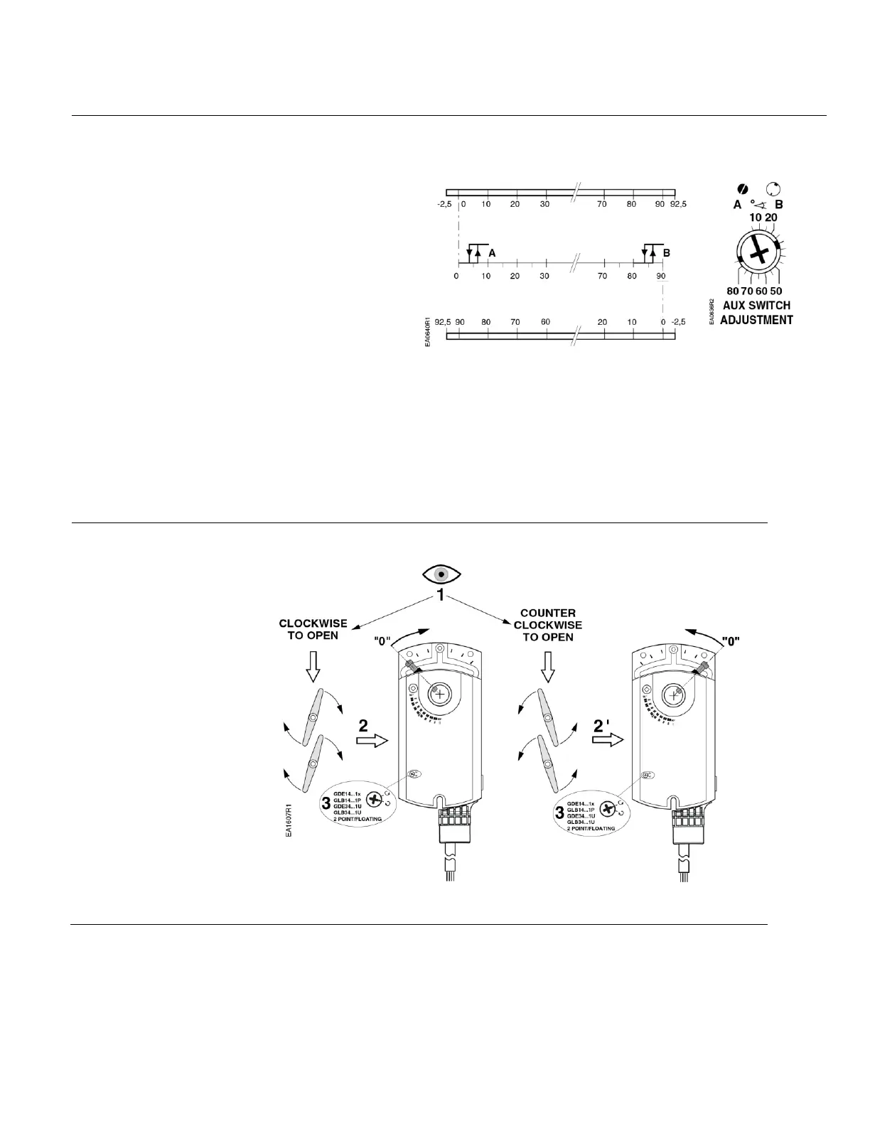
Figure 13 shows the adjustable switching values for Auxiliary Switches A and B.
Actuator Scale:
Clockwise
Adjustment range for
Switches A and B
Setting interval: 5°
Switching hysteresis: 2°
Actuator Scale:
Counterclockwise
Figure 13. Adjustable Switching Values
for the Dual Auxiliary Switches.
NOTE: The auxiliary switch setting shafts rotate with the actuator. The scale is valid only
when the actuator is in the 0 position on clockwise motion.
Use the long arm of the † (AUX SWITCH ADJUSTMENT) to point to the position of Switch A. Use
the narrower tab on the red ring to point to the position of Switch B.
Rotation Direction
GDE14x.1P, GDE34x.1U
Two-position/Floating
Control
Figure 14. Setting the Rotation Direction.

 Loading...