OpenAir® GDE Enhanced Non-Spring Return Rotary Electric Damper Actuator Technical Instructions
Document Number 155-784
October 20, 2016
Siemens Industry, Inc. Page 9
Rotation Direction
Switch
Counterclockwise Clockwise
Figure 15. Direction of Rotation Switch.
The factory setting is clockwise.
The direction of rotation switch should match the damper rotation movement.
Dual in-Line Package
(DIP) Switches
GDE16x.1P
Raise the protective cover from left to right to locate the DIP switches. See
Figure 9 for the location of the cover.
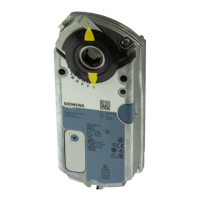
Modulating
control signal selection
Figure 16.
0 to 10 Vdc
Position
(Factory Setting).
To change the control signal from the factory setting (0 to
10 Vdc), move the first DIP switch to the UP (2-10)
position.
Figure 17.
OFF Position
(Factory Setting).
The factory setting is 0 (OFF).
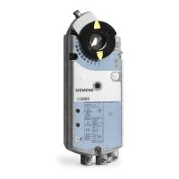
When mechanical angle of rotation is limited, the self-adapt
switch (middle DIP switch) may be turned ON so that the
limited range will become the new 0 to 100% for the
actuator logic. In this case, 0 to 100% is not equal to 90°
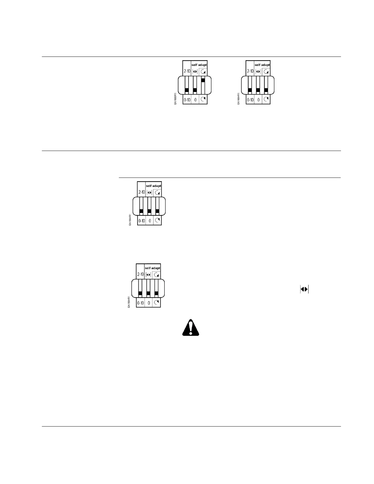
CAUTION:
When turning the self-adaptive feature on or
after the software reset with the feature on, the
actuator will enter a five-minute calibration
cycle as the actuator adjusts to the rotation
limits of the system. A software reset happens
after power on or may be caused by
electrostatic discharge (ESD) at levels of 2kV
and above.
The self-adapt capability will scale the control signal
selected, either a 0 to10 Vdc or a 2 to 10 Vdc signal, within
the adjusted mechanical range. The feedback signal will
also reflect the control signal selected, either a 0 to 10 Vdc
or a 2 to 10 Vdc.

 Loading...