d. Documentation package
• P-O-P Vector assembly drawing
• P-O-P Vector Switch unit drawing
• Installation / check-out instruction (this document)
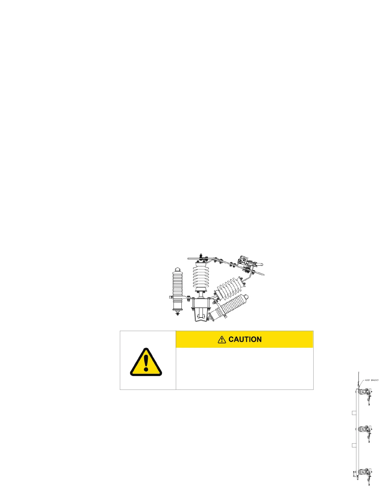
2. Uncrate the Siemens P-O-P Vector Switch and inspect carefully for shipping damage.
Inspect for:
a. Insulators that are chipped, cracked, etc.
b. Bent and/or broken hot parts
c. Bent and/or broken interrupters
d. Any missing items. See P-O-P Vector assembly drawing for BOM.
B. Installation instructions:
1. Drill two (2) mounting holes that are 11/16" in diameter located per customer construction
standards and spaced per Siemens P-O-P Vector assembly drawing.
2. Install the mounting bolts in the holes (mounting bolts not furnished).
3. Cut the hinge ties.
4. If lightning arrestors (supplied by the customer) are required, some customers prefer
to mount and make-up the arrestors while the switch is still on the crate base.
5. Lift the switch unit and mount it on the pole, over the previously installed mounting
bolts and tighten bolts until the split washer is flattened. Keyhole slots for this purpose
have been machined in the mounting brackets. Remove blade ties from all three jaw
assemblies so that the switch can be operated.
NOTE: Be very careful when lifting the switch unit not to damage the interrupters
or hot parts.
6. Ground the switch unit using #2 or larger copper wire. A grounding point (1/2-13 tapped
hole) is provided in the pole mounting bracket.
Phase-over-phase Vector® group-operated switches (600 and 900 A) Instruction Manual
5
It is the customer's responsibility to adjust arrestor
brackets, arrestors, ground lead wires and "Hot" lead
wires to provide proper phase to ground and phase to
phase clearance.