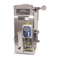
The Siemens PolyBlend PB200-0.4 is a unit designed for precise polymer dosage, mixing water regulation, and uniform dilution and activation. It operates continuously online, feeding the prepared solution to the point of use. The unit ensures that neat polymer from the metering pump and dilution water, controlled by a solenoid valve, enter the mixing chamber where dilution and activation occur, producing a ready-to-use solution.
Function Description:
The PolyBlend PB200-0.4 performs several key functions:
- Polymer Dosage: Accurately meters polymer into the mixing chamber.
- Mixing Water Regulation: Controls the flow of dilution water.
- Dilution and Activation: Ensures uniform mixing and activation of the polymer.
- Continuous Operation: Designed for continuous online use.
- Solution Delivery: Feeds the prepared polymer solution to the application point.
Neat polymer dosage rate can be adjusted either at the pump face or via an electronic controller (REM-1E, SCR, etc.). Primary and post-dilution water flows are managed by individual flow control valves.
Important Technical Specifications:
The device is equipped with a differential pressure switch, factory-set to ensure sufficient water flow before the polymer pump is energized. This safety feature prevents overfeeding neat polymer without proper dilution.
Pump Specifications (Example for a 2 GPH pump):
- Desired Solution: 100 GPH (380 LPH) of 0.5% polymer solution.
- Neat Polymer Requirement: 0.5 GPH (1.9 LPH).
- Pump Capacity Usage: 25% of a 2 GPH (7.6 LPH) pump.
- Polymer Concentration Limit: Do not exceed 1% polymer concentration in the PolyBlend.
Electrical Specifications:
- Power: 120 VAC/1 Phase, 60 Hz/6 Amps.
- Motor: Mixer motor, 1/6 HP, 1725 RPM.
- Controller: Digital Display Pump Controller (REM-1D).
- Input Signal: +4-20mADC (input by others).
Physical Dimensions (Overall):
- Width: Approximately 15.62 inches (front view), 16.63 inches (side view).
- Height: Approximately 24.55 inches.
Usage Features:
Start-Up Procedure:
- Switch the pump to external mode at the pump face.
- Prime the polymer pump using the provided priming kit.
- Place the unit power switch in the Off position.
- Energize the power circuit; the solenoid opens, allowing the mixing chamber to fill with water by opening the primary dilution water control valve.
- Note: Do not turn the mixer motor on until the chamber is filled with water; running dry will damage the mechanical seal.
- Place the unit power switch in the On position; the mixing chamber motor starts.
- Access the REM-1E controller to turn the pump On/Off and adjust polymer output. Output can also be adjusted at the pump face by varying the stroke length.
- Note: For optimal pump performance, keep the stroke frequency as high as possible by decreasing the stroke length setting. More frequent, shorter strokes are preferred over fewer, longer strokes. If the stroke length is too short, pump prime may be affected.
- Adjust water flow at the mixing chamber by turning the control valve. The other control valve should be used for post-dilution adjustment, if applicable.
- Note: Do not run the polymer pump unless water flow is established; polymer alone can plug discharge plumbing.
Differential Pressure Switch Adjustment:
The differential pressure switch ensures sufficient water flow before the polymer pump is energized. This safety feature prevents overfeeding neat polymer without proper dilution.
- Turn the PolyBlend rotameter until water flow is at maximum on the flow gauge.
- Screw in the differential pressure knob until the red alarm light goes on.
- Back off the differential pressure knob until the red alarm light goes off.
- For very close flow control, leave the knob at this setting (any loss of flow will disable the pump). For a more "forgiving" system, turn the knob another 1-2 turns (more flow can be lost before the pump is disabled).
- To test sensitivity, turn off the water at the source or the solution at the discharge. The float in the flow meter will fall, and the pump will be disabled.
- Set the rotameter for the desired flow and retest.
REM-1E Digital Display Pump Controller:
This controller serves as a remote control station or a proportional pump controller (4-20 mA input). It can vary the output of LMI Series AA7, A7, B7, or C7 metering pumps when in external mode. It connects via a 4-conductor cable and is powered by a 15 VDC source from the LMI pump. The controller output consists of 80 ms contact closures, triggering the LMI pump. In internal mode, output is 0-100 strokes-per-hour (sph) or strokes-per-minute (spm), adjusted via pressure-sensitive keys. In external mode, output is proportional to a 4-20 mA analog input signal. It features accurate solid-state microprocessor core technology, easy push-button control, multiple control options, and a durable NEMA 4X enclosure.
- Output Adjustment Controls: The uppermost knob controls speed (percent of maximum strokes per minute), and the largest knob below controls stroke (percent of maximum Liquifram travel).
- Priming: Hold a syringe firmly in the fitting and pull back on the plunger until a small amount of polymer is drawn into the syringe.
- Calibration: If required, disconnect the polymer suction line, connect a hose to the pump input, place the free end in a graduated cylinder, fill with polymer, run the pump to exhaust air, refill the cylinder, start timing, and record the volume pumped to adjust controls.
Maintenance Features:
Safety Precautions:
- Always wear protective clothing, face shield, safety glasses, and gloves when working near or performing maintenance on the pump. Refer to the MSDS Sheet from the polymer supplier for additional precautions.
- Ensure the control panel is grounded to avoid electrical shock or damage.
- Before servicing, turn off all power and assure a "lockout" to avoid possible electrical shock.
- Disconnect external power to the control panel before removing or replacing fuses.
General Maintenance:
- Cleaning: Periodic cleaning of the solenoid valve is recommended (at least every 12 months or 500,000 cycles). Sluggish operation, excessive leakage, or noise indicates a need for cleaning or repair. Clean the valve filter or strainer when cleaning the valve.
- Preventative Maintenance:
- Keep media flowing through the valve free from dirt and foreign matter.
- Operate the valve at least once a month when not in service to ensure proper opening and closing.
- Periodically inspect internal valve parts for damage or excessive wear (at least every 12 months or 500,000 cycles).
Troubleshooting:
- No Water Flow: Check for closed valves on the water supply, blocked solenoid valve, clogged discharge line, or closed rate control valve. Corrective actions include opening valves, disassembling and cleaning valves, and opening any closed valves.
- Pump Won't Pump Chemical: Check if the pump is turned OFF, if there is no water flow, if the pump discharge line is blocked, if back pressure is too high, or if there is not enough water flow. Corrective actions include turning the pump ON, ensuring all water valves are open, cleaning the discharge line, reducing back pressure, or increasing water flow.
- Clogged Injection Check Valve: Check for debris or clumps in polymer or if the valve is stuck open. Corrective actions include checking polymer supply for contamination and cleaning the valve.
- Pump Won't Stop: Check if water flow is still established or if the pump is in internal mode. Corrective actions include shutting off the water valve or power to the unit and switching the pump to external mode.
Seal Ring, Ball, and Injection Check Valve Spring Replacement:
- Depressurize, drain, and disconnect discharge and suction lines. Place the suction tubing into mineral oil, turn on the pump to flush the head assembly, then lift the tubing out of the oil and pump air to purge the head.
- Disconnect tubing connections and fittings, remove the worn seal ring and ball, and loosen sealing by prying side to side.
- Install new seal ring and ball, noting correct orientation.
- Install the new spring valve in the Injection Check Valve.
Check Pump for Proper Zeroing (Stroke Knob):
- With the pump running, turn the stroke knob counter-clockwise toward zero.
- Listen for quiet operation; no clicking should occur at the zero position.
- If clicking continues or stops before zero, the pump must be reset.
Liquifram (Diaphragm) Replacement:
When replacing the Liquifram, also replace valve balls, seal rings, and the injection check valve spring.
- Depressurize, drain, and disconnect lines. Flush the head assembly with mineral oil, then purge with air.
- Start the pump, set the stroke knob to zero, and turn off the pump.
- Unscrew the Liquifram by grasping the outer edge and turning counter-clockwise. Discard the old Liquifram disk and check that the size code matches the replacement.
- Reinstall the disk, ensuring the alignment pin seats in the recessed hole.
- Warning: Take care not to scratch the Teflon face of the new Liquifram.
- Start the pump, turn the stroke knob to the setting indicated on the Stroke Setting Chart for the pump model, and screw on the new Liquifram clockwise until the center buckles inward. Stop the pump.
- Adjust the Liquifram by screwing it in or out so that its center is flush with the outside of the spacer edge.
- Remount the pump head to the spacer using four screws, tightening in a crisscross pattern. Recheck and tighten after one week of operation.
Solenoid Valve Maintenance:
- Coil Replacement: Turn off electrical power, disconnect coil leads. Remove the gold ring by inserting a screwdriver and twisting counter-clockwise. Lift off the solenoid. Replace the old coil with a new one of correct watt, voltage, and class. Reassemble by sliding the new solenoid over the plunger tube assembly, pressing the gold ring against the adhesive data label, and reconnecting the electrical circuit.