Do you have a question about the Siemens CPU 1513-1 PN and is the answer not in the manual?
Overview of the SIMATIC S7-1500 documentation structure and access methods.
Information on Siemens industrial security functions and customer responsibilities for cyber threat prevention.
Overview of important new firmware functions for the CPU compared to predecessor versions.
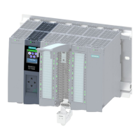
Describes the SIMATIC S7-1500 as a modular control system and lists its areas of application.
Details the article number and the specific technical properties of the CPU 1513-1 PN.
Lists and describes the various firmware functions supported by the CPU 1513-1 PN.
Describes the front view of the CPU, including LEDs, display, and control buttons.
Explains the function and meaning of the operating mode buttons on the CPU.
Details the pin assignment and connection for the 24 V DC power supply.
Describes the PROFINET interface, its ports, and autonegotiation behavior.
Explains the assignment and labeling of the CPU's MAC addresses for its PROFINET interfaces.
Provides a block diagram of the CPU 1513-1 PN, illustrating its components and connections.
Describes the LED indicators on the CPU for displaying operating status and diagnostic information.
Explains the various combinations of colors and states for the RUN/STOP, ERROR, and MAINT LEDs.
Details the scenarios for the LINK RX/TX LEDs on the PROFINET ports, indicating connection status.
Explains the function of the STOP ACTIVE LED and its implications for switching the CPU to RUN mode.
Lists general technical data for the CPU, including product designation, firmware version, and I&M data.
Details product functions like I&M data support and isochronous mode capabilities.
Lists typical processing times for bit operations, word operations, and arithmetic calculations.
Specifies ambient temperature limits for operation, storage, and transportation, as well as altitude limits.
Outlines various levels of protection for configuration data, display, and program blocks.
Presents dimensional drawings of the CPU module for installation purposes, showing front, side, and open panel views.
| Product type designation | CPU 1513-1 PN |
|---|---|
| Product family | SIMATIC S7-1500 |
| Firmware version | V2.0 |
| Engineering with | TIA Portal |
| Supply voltage | 24 V DC |
| Input current | 0.3 A |
| Memory for program | 300 KB |
| Memory for data | 1.5 MB |
| RAM | 1 MB |
| Program Memory | 300 KB |
| Data Memory | 1.5 MB |
| Number of PROFINET ports | 2 |
| PROFINET interface | Yes |
| PROFIBUS DP master | No |
| OPC UA | Yes |
| Web server | Yes |
| Weight | 0.5 kg |
| Number of connections | 64 |
| Number of IO controllers | 1 |
| Number of IO devices | 128 |
| PROFINET IO controller | Yes |
| PROFINET IO device | Yes |
| PROFINET IRT | Yes |
| PROFIBUS DP slave | No |
| Number of motion control resources | 4 |
| Integrated Functions | Motion control, PID control |
| Dimensions WxHxD | 35 mm x 147 mm x 129 mm |
| Operating temperature | 0 °C to 60 °C |