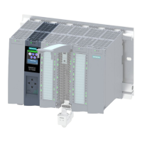
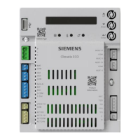
CPU 1513-1 PN (6ES7513-1AM03-0AB0)
Equipment Manual, 11/2022, A5E40881673-AC
30
Connecting up
4
This section provides information on the terminal assignment of the individual interfaces and
the block diagram of the CPU1513-1PN.
24VDC supply voltage (X80)
The connector for the power supply is plugged in when the CPU ships from the factory.
The following table shows the signal names and the descriptions of the pin assignment of
the24VDC supply voltage.
Table 4-1Pin assignment24VDC supply voltage
View
Connector
Signal name
1)
Description
1 1L+ +24VDC of the supply voltage
2 1M Ground of the supply voltage
3 2M Ground of the supply voltage for loop-through
2)
Figure
4 2L+ +24VDC of the supply voltage for loop-through
2)
1)
1L+ and 2L+ as well as 1M and 2M are bridged internally
2)
Maximum 10A permitted
If the CPU is supplied by a system power supply, it is not necessary to connect the 24V
supply.

 Loading...


