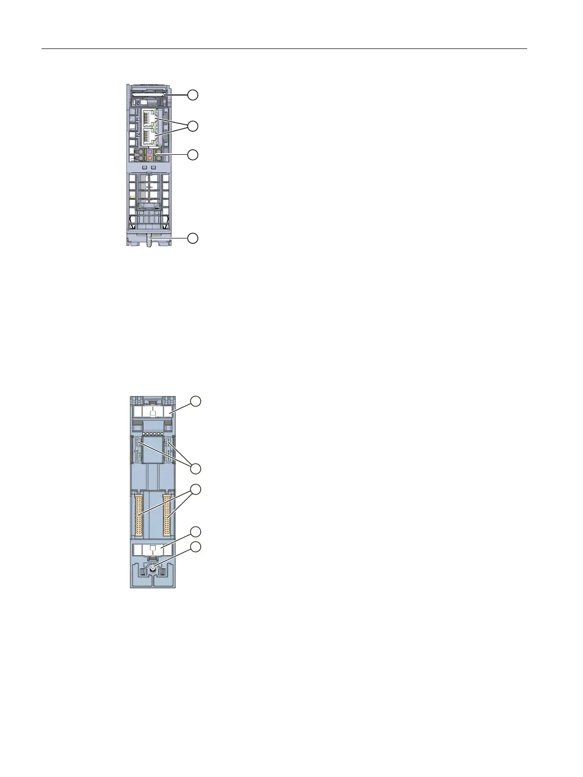
① Slot for the SIMATIC memory card
② PROFINET IO interface (X1) with 2 ports
③ Connection for supply voltage
④ Fixing screw
Figure 3-5View of the CPU1513-1PN – bottom
3.5.3 Rear view of the CPU
The following figure shows the connection elements on the back of the CPU1513-1PN.
① Shield contact surface
② Plug-in connection for power supply
③ Plug-in connection for backplane bus
④ Fastening screw
Figure 3-6View of the CPU1513-1PN - rear
28
CPU 1513-1 PN (6ES7513-1AM03-0AB0)
Equipment Manual, 11/2022, A5E40881673-AC
Product overview
3.5 Operating and display elements
 Loading...