The table below shows how the MAC addresses are assigned.
Table 4-2Assignment of the MAC addresses
Assignment Labeling
MAC address 1 PROFINET interface X1
(visible in STEP7 for accessible devices)
• Front, lasered
• Right side, lasered (start of number
range)
MAC address 2 Port X1P1R (required for LLDP, for
example)
• Front and right side, not lasered
MAC address 3 Port X1P2R (required for LLDP, for
example)
• Front, not lasered
• Right side, lasered
(end of number range)
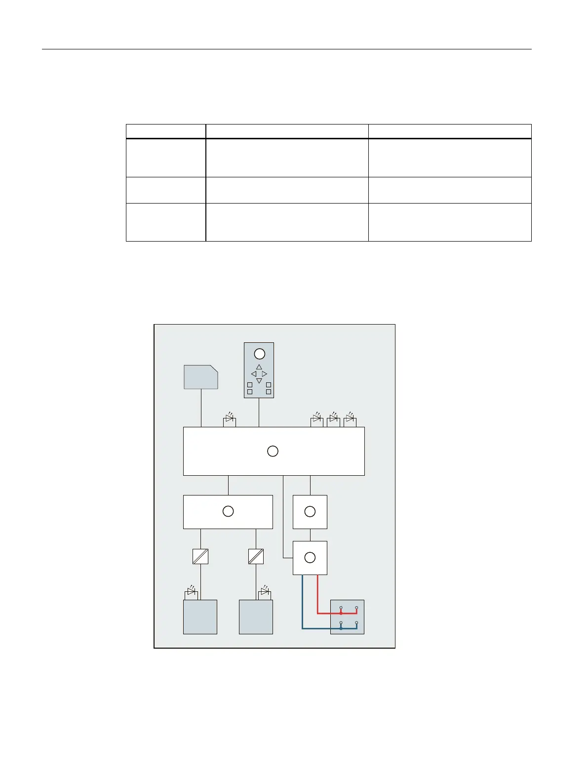
Block diagram
The following figure shows the block diagram of the CPU1513-1PN.
3
4
2
5
1
L+
M
X50
X1 P1
PN
X1 P1R
X1 P2
R/S ER MT
PN
X1 P2R
X80 DC 24 V
SA
① CPU with control and operating mode
buttons
X80 24 V DC Infeed of supply voltage
② Electronics L+ 24 V DC supply voltage
32
CPU 1513-1 PN (6ES7513-1AM03-0AB0)
Equipment Manual, 11/2022, A5E40881673-AC
Connecting up
 Loading...