Document No. 129-095
Installation Instructions
September 24, 2009
Page 2 of 3 Siemens Industry, Inc.
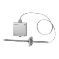
3. Draw a line between opposite drill marks,
farthest from each other, and make a drill mark
with the punch, at the intersection of the two
lines.
4. Drill four 1/8-inch holes for the mounting screws
at the points labeled “A”, and a 7/8-inch
diameter hole at the point labeled “B” (see
Figure 2).
Figure 2. Mounting Screw Locations.
5. Secure the flange to the duct using the screws
included with the flange and insert the probe into
the duct. Do not tighten the mounting screw at
this time.
Transducer
1. Remove the cover from the transducer head
unit.
2. Hold the base on the duct or structure to which it
is to be mounted and mark the center positions
of the four mounting holes.
NOTE: Make sure there is enough slack in the
probe’s cable so that, if necessary, the
probe can be removed for servicing or
replacement.
3. Make drill hole marks with the punch at the
mounting hole points, and drill four 1/8-inch
holes.
4. Secure the transducer head to its mounting
location with four #8 × 1/2-inch sheet metal
screws.
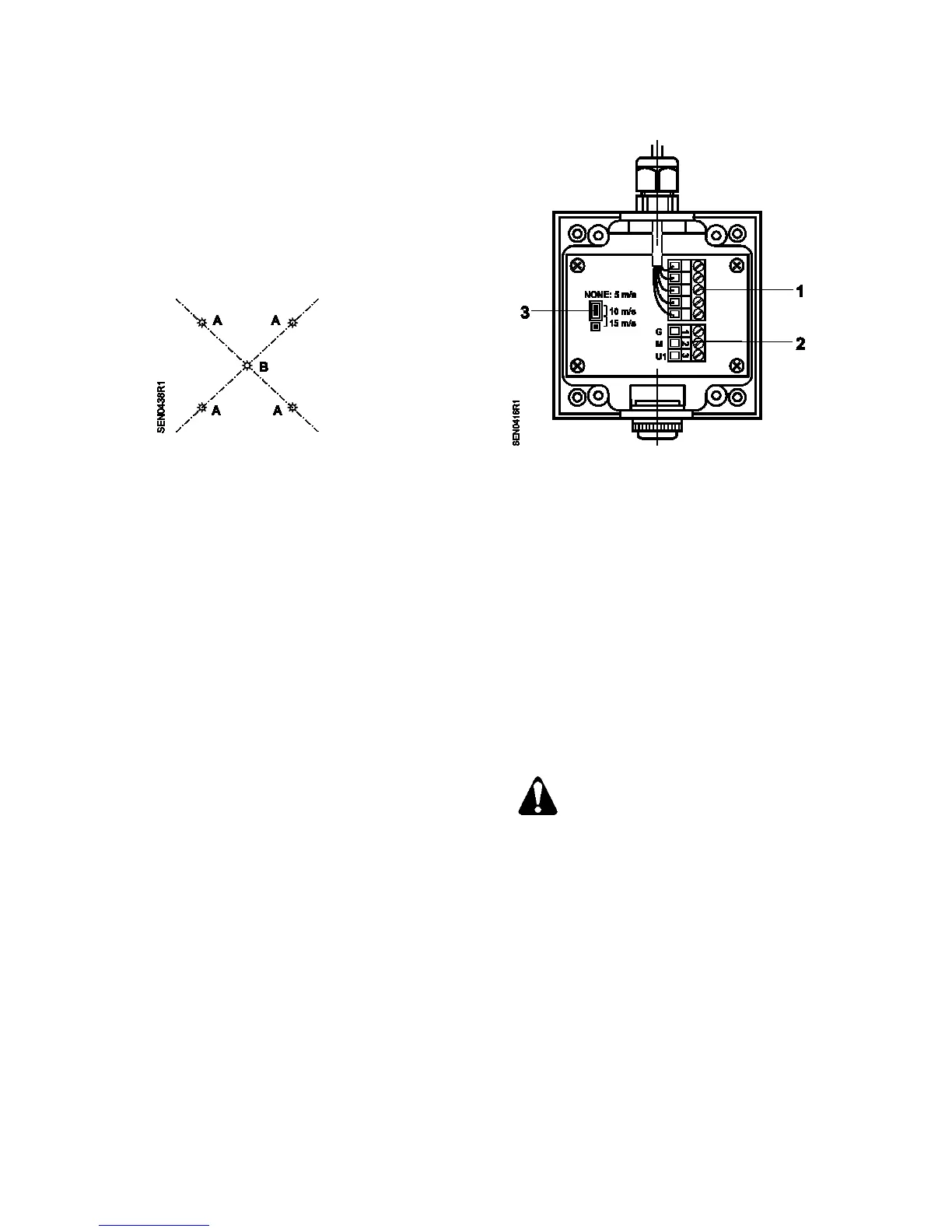
5. Set jumper for desired airflow range (see
Figure 3).
6. Connect the Field wiring to the transducer head
connector (see Figure 3.)
1 Terminal block for connection to the
immersion stem
2 Terminal block for connection to controller
3 Plug-in unit for setting the three velocity
ranges. The following applies:
No plug-in jumper = 0 to 5 m/s
Plug-in jumper on 1 and 2 = 0 to 10 m/s
(factory setting)
Plug-in jumper on 2 and 3 = 0 to 15 m/s
Figure 3. Wiring and Setting Elements.
7. Reinstall the cover
The sensor head connections are not
protected against 24 Vac operating
voltage.
If the unit power supply lead being
connected to terminal G is live during
the installation of the sensor, contact
with any of the sensor head terminals
can irreparably damage the unit.
8. Set the probe’s depth of insertion and position
the arrow on the probe cap so that it points in
the direction of the airflow.
9. Tighten the mounting screw located on the side
of the mounting flange (see Figure 4).
The installation is now complete.
.
 Loading...


