EasyManua.ls Logo

Siemens QVM62.1 User Manual

Siemens QVM62.1
4 pages
To Next Page IconTo Next Page
Page #1 background imageLoading...
Page #1 background image
QVM62.1
Technical Instructions
Document No. 155-006
October 26, 2006
Air Velocity Sensor
Siemens Industry, Inc.
Description
This sensor is used to control the air velocity to a constant value, balance out pressure
fluctuations (supply or exhaust air control), or to monitor the flow in air ducts. It is
primarily used for modulating fan control in primary applications to set the basic volume
flow.
Application
The QVM62.1 Sensor records the air velocity as a measured value and converts it to
an active 0 to 10 Vdc output signal. There are three measuring ranges available:
0 to 16 ft/s (0 to 5 m/s)
0 to 33 ft/s (0 to 10 m/s)
0 to 49 ft/s (0 to 15 m/s).
The sensor measures a point (that is it measures the values at a specific location in the
flow profile. For recording the mean air velocity in the duct, the sensor’s immersion
depth is the key measure. The immersion depth depends on the flow profile.
The measurement principle is based on the anemometric measurement principle. The
specially developed thin film sensing element of the QVM62.1 is almost totally
independent from the flow direction and is insensitive to almost any kind of dirt in the
airflow.
Product Number
QVM62.1
Operation
The air velocity sensor consists of:
Immersion stem with sensor head and sensing element
Extension pipe with fitting
Immersion stem end with flow direction arrow
Adjustable connecting flange
Transducer
Connection cable, screened, four-core, 3 feet (1 m) long

Other manuals for Siemens QVM62.1

Question and Answer IconNeed help?

Do you have a question about the Siemens QVM62.1 and is the answer not in the manual?

Siemens QVM62.1 Specifications

General IconGeneral
Power supplyAC 24 V
Protection classIP54
Compatible withSiemens valves
MaterialPlastic
Product typeValve actuator
Control signalDC 0...10 V
MountingOn valve

Summary

Product Description and Application

Sensor Description

Details the sensor's function in controlling air velocity and modulating fan control in primary applications.

Application and Measuring Ranges

Explains how the QVM62.1 sensor records air velocity and converts it to a 0-10 Vdc signal, listing available ranges.

Operation and Components

Sensor Operation Principle

Describes the sensor's measurement principle, independence from flow direction, and insensitivity to dirt.

Sensor Components List

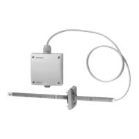
Lists the parts that constitute the air velocity sensor, including immersion stem, extension pipe, and transducer.

Measuring Range Selection

Details how measuring ranges are selected using plug-in jumpers on the terminal block.

Technical Specifications

Power Supply and Data Output

Specifies operating voltage, frequency, power consumption, output impedance, and signal output characteristics.

Measuring Data and Accuracy

Covers adjustable measuring ranges, accuracy at specific conditions, permissible air velocity, and time constant.

Line Length Limitations

Provides permissible cable lengths to the controller based on AWG gauge and length to the sensor head.

Installation and Environmental Guidelines

Connections and Protection

Details screw connections, electrical and mechanical degrees of protection for the transducer and sensor head.

Environmental and Storage Conditions

Specifies climatic, mechanical, and chemical conditions for operation, storage, and transportation.

Materials, Colors, and Weight

Lists materials and colors used for housing, pipes, and sensor, along with the product's weight.

Engineering Notes for Placement

Provides guidance on optimal sensor placement within ductwork, avoiding disturbances like dampers or changes.

Mounting, Commissioning, and Wiring

Mounting and Installation Instructions

Guides on mounting the immersion stem, connecting pipes, and attaching the flange for proper installation.

Commissioning Checks

Advises on checking wiring and air velocity range settings before commissioning the sensor.

Wiring Diagram and Connections

Illustrates the wiring diagram, showing connections for operating voltage, ground, and signal output.

Physical Dimensions

Presents detailed dimensions of the QVM62.1 sensor in inches and millimeters for installation planning.

Related product manuals