Technical Instructions QVM62.1 Air Velocity Sensor
Document Number 155-006
October 26, 2006
Page 2 Siemens Industry, Inc.
Operation
(Continued)
A scale with 0.20 in (0.5 cm) grating on the immersion stem and the extension pipe
indicates the immersion depth.
The connecting flange is used to attach and seal the immersion stem on the duct wall.
A plastic housing with removable cover accommodates the transducer. It can be
screwed to a flat surface.
The sensor cable is connected: the sensor and the transducer are a unit.
The measuring ranges are selected by inserting or removing a plug-in jumper.
Protection against false wiring is provided related to own voltages. (Measuring output
U1 is short-circuit proof.) The sensor head connections are not protected against 24
Vac operating voltage.
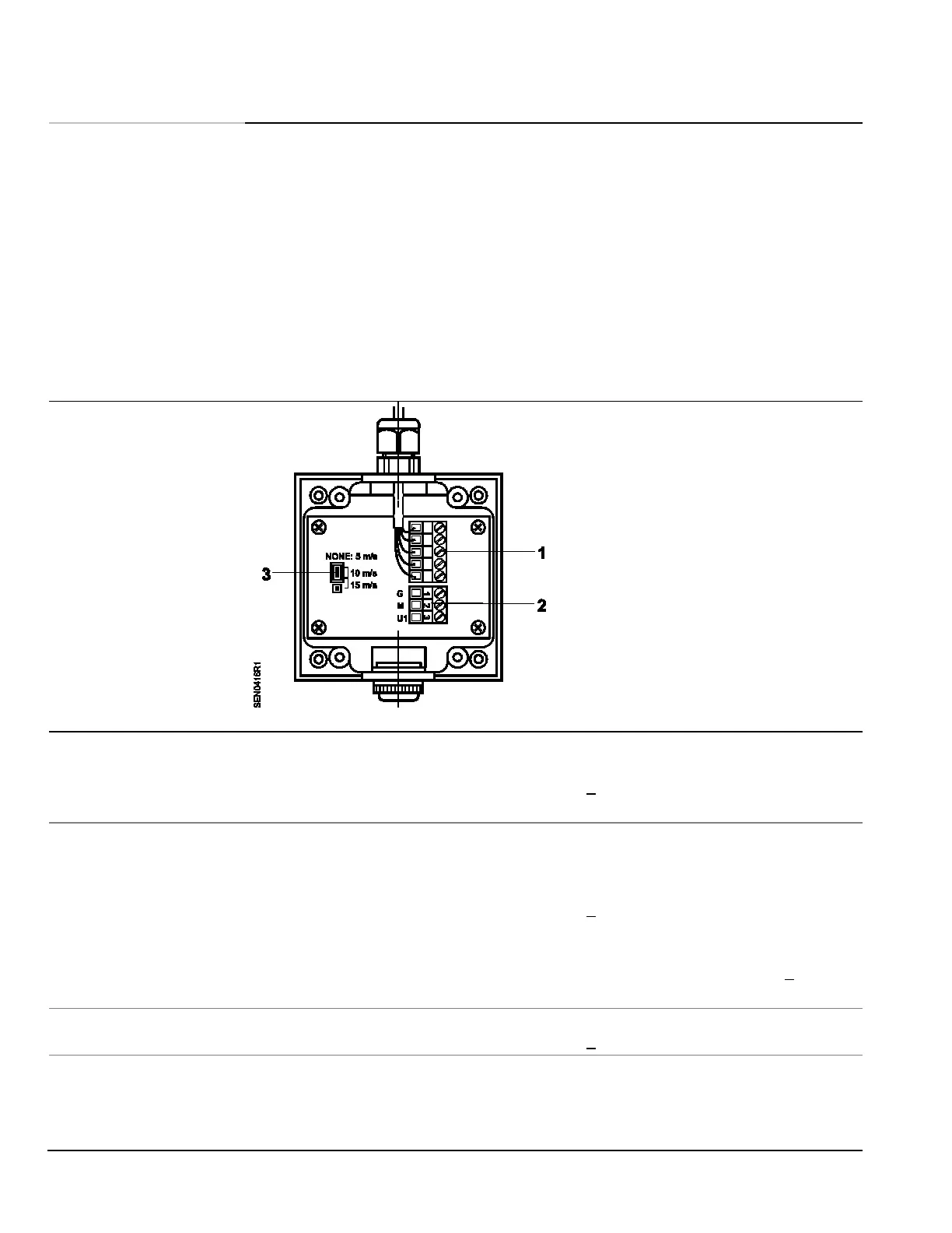
Components
Figure 1. Wiring and Setting Elements.
1 Terminal block for connection to the
immersion stem.
2 Terminal block for connection to the
controller.
3. Plug-in unit for setting the three velocity
ranges.
No plug-in jumper = 0 to 16 ft/s
(0 to 5 m/s)
Plug-in on 1 and 2 = 0 to 32 ft/s
(0 to 10 m/s)
(Factory setting)
Plug-in on 2 and 3 = 0 to 49 ft/s
(0 to 15 m/s)
Specifications
Power supply
Operating voltage 24 Vac +/- 20%
Frequency 50/60 Hz
Power consumption < 5 VA (maximum 200 mA)
Output impedance <20 ohm
Measuring ranges, adjustable 0 to 16 ft/s (0 to 5 m/s)
0 to 33 ft/s (0 to 10 m/s)
(factory setting)
0 to 49 ft/s (0 to 15 m/s)
Measuring accuracy at 68°F (20°C), 45% rh, + 0.7 ft/s (0.2 m/s + 3% of measured
1013 hPa value)
Permissible air velocity 66 ft/s (20 m/s)
Direction dependence < 0.3% of measured value at< + 10°
Time constant t
90
at 10 m/s ca. 4 seconds
Current + 1 mA
Line length Permissible length to controller at:
20 AWG copper cable 164 ft (50 m)
18 AWG copper cable 492 ft (150 m)
16 AWG copper cable 984 ft (300 m)
Line length to the sensor head 3 ft (1 m) (prewired)
 Loading...


