QVM62.1 Air Velocity Sensor Technical Instructions
Document Number 155-006
October 26, 2006
Siemens Industry, Inc. Page 3
Mechanical Screw connection
Electric Screw terminal, maximum 2 × 18 AWG
Degree of protection provided by enclosures
as per EN 60 529
Transducer IP 42
Sensor head IP 20
Degree of protection as per EN 60 730 III
Temperature 23°F to 113°F (-5°C to 45°C)
Humidity (non-condensing) <95% rh
Mechanical conditions Class 3M2
Chemical conditions Class 3C2
Storage (transducer and immersion stem)
Temperature 23°F to 113°F (-5°C to 45°C)
Humidity (non-condensing) <95% rh
Mechanical conditions Class 1M2
Transportation
Temperature 23°F to 113°F (-5°C to 45°C)
Humidity (non-condensing) <95% rh
Mechanical conditions Class 2M2
Housing bottom Polycarbonate, RAL 7001 (silver-gray)
Housing cover Polycarbonate, RAL 7035 (light gray)
Sensor pipes Polycarbonate, RAL 7001 (silver-gray)
Sensor head, extension, enc Polycarbonate, RAL 7035 (light gray)
Connecting flange Polycarbonate, RAL 7001 (silver gray)
Sensor Silicone-free
With packaging 12 oz (0.352 kg)
Engineering Notes
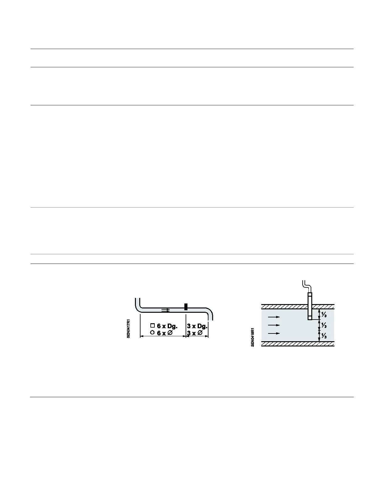
Place the sensor in a location where the airflow is quiet. Do not place it close to
dampers, registers or duct direction changes.
Figure 2. Sensor Placement.
Use a transformer with safety extra-low voltage (SELV) and separate winding for 100%
ON-time.
Observe all local safety rules and regulations pertaining to sizing and protecting
transformers.
Note the permissible line length to the controller.
 Loading...


