Do you have a question about the Siemens QMX3.P30 and is the answer not in the manual?
Introduces wall-mounted sensors and room operator units for KNX PL-Link, S-mode, and LTE-Mode.
Lists core functionalities like energy efficiency, sensor measurements, and control capabilities.
Details sensors, room operator units, and accessories with their features.
Explains compatibility with KNX PL-Link and KNX S-mode systems.
Describes standard base plates and optional metal-reinforced base plates for mounting.
Covers conduit box dimensions, cable distances, and base plate screw requirements.
Provides engineering and commissioning notes for KNX PL-Link, S-mode, and LTE-Mode.
Advises on ideal placement, height, and environmental conditions for installation.
Details the steps for mounting the device over a conduit box, including sealing tubes.
Explains how to mount using a reinforced base plate on a cavity wall box with foam plate.
Illustrates wall mounting, 4-wire daisy chain wiring, and cable duct placement.
Shows the procedure for dismounting the device for servicing or replacement.
Guides on inserting and removing labels for specific keys on QMX3.P02 and QMX3.P37 models.
Covers KNX PL-Link wiring, regulations, and a caution against AC 230V connection.
Outlines requirements for commissioning, including running the automation station and loading applications.
Details the process for addressing, connection testing, and factory resetting devices.
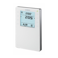
Explains commissioning for devices without a display, including addressing and connection testing.
Describes how to perform a factory reset on devices without a display, noting it's irreversible.
Describes the plug & play process where the unit automatically communicates with the station.
Details the "UCFG" display message indicating faulty configuration and the need for manual commissioning.
Outlines addressing and factory reset procedures for KNX commissioning.
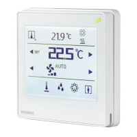
Explains the numbering of keys, LED display functions, and the operation of Light, Blinds, and Scenes keys.
Details the different display segments (A, B, C, D, E) and their corresponding functions.
Explains the function of each key, including temperature display, setpoint adjustment, and mode selection.
Provides instructions for cleaning the device using solvent-free agents and a soft cloth.
Lists detailed technical data including supply voltage, power consumption, and sensor specifications.
Covers ports, Baud rate, protection classes, ambient conditions, and standards compliance.
Details color, weight, FCC rules, and warnings for the device.
Explains the KNX/PL-Link plug wiring, emphasizing non-interchangeable wires and bus connection rules.
Describes how to connect the ABT and OCI 702 service interface for loading applications or service.
Provides detailed mechanical dimensions of the wall-mounted unit and its base plate.
Outlines the proper disposal of the electronic device according to European directives.
| Brand | Siemens |
|---|---|
| Model | QMX3.P30 |
| Category | Accessories |
| Language | English |