Installation Instructions
Document No. 129-903
October 4, 2013
Air Differential Pressure Sensors
Item Number 129-903, Rev. BA Page 1 of 2
Product Description
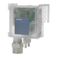
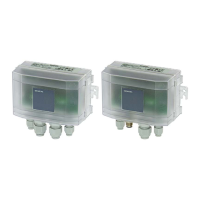
The Siemens QBM Series Air Differential Pressure
Sensors use a well-proven ceramic technology.
They deliver temperature-compensated sensor
signals for registering airflow in HVAC systems and
for the measurement of differential pressures in
environmental, laboratory and cleanroom
applications.
Product Numbers
Product Number Percent
Accuracy
Pressure
Range
Inches WC
(Water
Column)
QBM3100U025U +/- 0.25
QBM3100U1 1
QBM3100U2.5 2.5
QBM3100U5 5
QBM3100U10
+/-1% FS
10
Contents
• Sensor
• Conduit Adapter
Warning/Caution Notations
WARNING:
Personal injury/loss of life may
occur if you do not follow the
procedures as specified.
CAUTION:
Equipment damage/loss of
data may occur if you do not
follow the procedures as
specified.
Required Tools
• Small, Phillips screwdriver
• Small, flat-blade screwdriver
• Adjustable wrench
Expected Installation Time
30 minutes
Prerequisites
Even though the device is protected against electro-
magnetic interference, installation and cabling must
be carried out correctly to ensure interference
immunity.
• Use shielded cables for the signal and control
lines with the connecting lead of the shield
being kept as short as possible. The connection
point of the shielding depends on the existing
connection conditions.
• Never route signal and control cables together
with the trunk line or feeder cables of motors,
cylinder coils, rectifiers, and so on. The cables
must be routed in conductive and grounded
cable conduits. This applies especially to long-
distance cables, or environments where the
cables are exposed to strong radio waves from
broad casting stations.
CAUTION:
• Prior to mounting or removing the
sensor, verify that the system is
depressurized.
• Do not mount sensors in locations
subject to high pressure pulses.
• Significant thermal changes in the
sensor environment can lead to a zero
shift. As a result, the measuring value
displayed in a depressurized state will
read zero. This kind of drift can be
corrected by zero point reset.