Installation Instructions
Document No. 129-416
October 5, 2009
Q-Series Outdoor Air Relative Humidity
and Relative Humidity & Temperature
Item Number 129-416, Rev. BA Page 1 of 2
Product Description
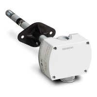
The Q-Series Outdoor Air Relative Humidity, and
Relative Humidity & Temperature Sensors monitor
and transmit changes in humidity and temperature to
the building control systems. These units are
especially suited for applications where precise,
stable humidity sensing is required. Standard
models available are 2% and 2% certified, for both
humidity only and combination humidity with
temperature sensing. Sensors are offered with either
4 to 20 mA or 0 to 10 Volt output signals.
Product Numbers
Part Number Description
Outdoor air humidity sensor (2%),
0 to 10 Vdc
Outdoor air humidity sensor (2%),
4 to 20 mA
Outdoor air humidity sensor (2%),
0 to 10 Vdc/Temp 0 to 10 Vdc
Outdoor air humidity sensor (2%),
0 to 10 Vdc/Temp 0 to 10 Vdc with
Outdoor air humidity sensor (2%),
4 to 20 mA/Temp 4 to 20 mA
Outdoor air humidity sensor (2%),
4 to 20 mA/Temp 4 to 20 mA with
Outdoor air humidity sensor (2%),
4 to 20 mA/Temp 4 to 20 mA, certified
Outdoor air humidity sensor (2%),
4 to 20 mA/Temp 4 to 20 mA, certified
Outdoor air humidity sensor (2%),
0 t 10 Vdc/Temp 0 to 10 Vdc, certified
Outdoor air humidity sensor (2%),
0 t 10 Vdc/Temp 0 to 10 Vdc, certified
Replaceable, certified sensor tip
US 1/2-inch rigid conduit adapter
Required Tools
• Phillips screwdrivers, sizes No. 1 and No. 2
• Medium flat-blade screwdriver
• Wire cutters/strippers
• Tape measure
• Medium-duty electric drill
• Drill bit for wall anchor hole
• Marker or pencil
• Two No. 10 screws and wall anchors
Expected Installation Time
30 minutes
Prerequisites
• Ensure that the appropriate field wiring is
installed.
Appropriate wiring is one or more twisted pair or
three conductor cables (plenum or non-plenum
as required) within the maximum wiring run
length for the humidity/temperature controller.
The maximum recommended length is 750 feet
(229 m).
• Ensure that all wiring complies with National
Electric Code (NEC) and local regulations.
Installation
1. Determine where the sensor is to be located and
install the Sun Shield, AQF3100, as shown in
Figure 1. The installation surface determines
which mounting components are to be used.
NOTE: The shield must be mounted vertically
as shown in Figure 1.
2. Remove sensor cover and install plug in
knockout next to sensing probe. See
Figure 1 (2).
3. Pull the field wiring through the conduit and into
the sensor base. See Figure 2.