EasyManua.ls Logo

Siemens QFM2100 User Manual

Siemens QFM2100
3 pages
To Next Page IconTo Next Page
Page #1 background imageLoading...
Page #1 background image
Installation Instructions
Document No. 129-413
October 13, 2004
Q-Series Relative Humidity (RH) and
Relative Humidity & Temperature (RH/T) Duct Sensors
Product Description
Relative Humidity (RH) and Relative Humidity &
Temperature (RH/T) duct sensors monitor the
relative humidity or the relative humidity and
temperature in a duct, depending on the model.
Sensors are directly wired to the controller via
twisted pair and/or three conductor cables
(18 to 22 AWG). The number and type of cables
required depends on the model selected. All field
wiring is terminated in a terminal block on the sensor
body.
Product Numbers
Table 1. Relative Humidity Only.
Product
Number
Humidity
Signal
Accuracy
QFM2100 ±5%
QFM3100
0 to 10 Vdc
±2%
QFM2101 ±5%
QFM3101 ±2%
QFM4101
4 to 20 mA
±2% Certified
Table 2. Relative Humidity and Temperature.
Product
Number
Temperature
Signal
Humidity
Signal
Accuracy
QFM2160 ±5%
QFM3160 ±2%
QFM4160
0 to 10 Vdc 0 to 10 Vdc
±2% Cert.
QFM2171 ±5%
QFM3171 ±2%
QFM4171
4 to 20 mA 4 to 20 mA
±2% Cert.
QFM2110
Pt 1K
QFM2120
Ni 1K
QFM2140 T1 PTC
±5%
QFM3110
Pt 1K
0 to 10 Vdc
±2%
Applies to humidity only
NOTE: Sensor tips on QFM31… and QFM41…
models are field replaceable.
Additional Reference Documents
Product Number Technical Instructions
QFM21… 155-748
QFM3160 155-749
QFM4160 155-750
Required Tools
Phillips screwdrivers, #1 and #2
Wire cutters/strippers
Medium flat-blade screwdriver
Tape measure
Medium-duty electric drill
Marker or pencil
No. 26 (0.147-inch) drill bit
Small level
7/8-inch drill bit or hole saw
Two No. 8 × 1-inch sheet metal screws
Expected Installation Time
One hour
Prerequisites
Ensure that the appropriate field wiring is
installed.
Appropriate wiring is one or more twisted
pairs, or three conductor cables (plenum or
non-plenum as required), within the
maximum wiring run length for the individual
equipment controller. The maximum
recommended length is 750 feet (229 m).
Ensure that all wiring complies with National
Electric Code (NEC) and local regulations.
Mounting Information
Locate the sensor:
In the center of a duct.
Away from fans, corners, heating and cooling
coils, and so on.
Where it receives adequate airflow for proper
operation.
Item Number 129-413, Rev. 011 Page 1 of 3
Question and Answer IconNeed help?

Do you have a question about the Siemens QFM2100 and is the answer not in the manual?

Siemens QFM2100 Specifications

General IconGeneral
BrandSiemens
ModelQFM2100
CategoryAccessories
LanguageEnglish

Summary

Q-Series RH/T Duct Sensors Overview

Product Description

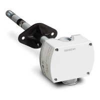
Details the function and wiring of RH and RH/T duct sensors for monitoring duct conditions.

Product Numbers and Specifications

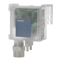
Lists available sensor models, signal types (0-10 Vdc, 4-20 mA), and accuracy ratings.

Required Tools for Installation

Lists all tools and hardware needed for installing the duct sensors.

Installation Prerequisites

Ensures proper field wiring and compliance with electrical codes before installation.

Mounting Location Guidelines

Provides recommendations for optimal sensor placement within a duct for accurate readings.

Installation Instructions

Sensor Mounting Bracket Installation

Details steps for attaching the sensor mounting bracket to the duct using screws.

Direct Sensor Installation

Explains how to mount the sensor directly to the duct without a separate bracket.

Wiring Connections

Covers attaching conduit/plenum wire and connecting field wiring to the sensor base.

Wiring Diagrams

RH Sensors 0-10 Vdc Wiring

Diagram for connecting RH sensors with a 0 to 10 Vdc signal output.

RH Sensors 4-20 mA Wiring

Diagram for connecting RH sensors with a 4 to 20 mA signal output.

RH/T Sensors 0-10 Vdc Wiring

Diagram for RH/T sensors outputting 0 to 10 Vdc for both temperature and humidity.

RH/T Sensors 4-20 mA Wiring

Diagram for RH/T sensors outputting 4 to 20 mA for both temperature and humidity.

RH/T Thermistor RTD 0-10 Vdc Wiring

Diagram for RH/T sensors using Thermistor RTD with a 0 to 10 Vdc output.

Related product manuals