Installation Instructions
Document No. 129-484
April 17, 2014
Series 2200 Temperature and Series
3200 Combination RH&T Room Units,
Item Number 129-484, Rev. JA Page 1 of 3
Product Description
These room units allow users to view and adjust
points in the controller using the room unit buttons
and digital display.
They work with various Terminal Equipment
Controllers (TECs) and Actuator Terminal
Controllers (ATECs) offered by Siemens Industry,
Inc. These devices incorporate a solid state or 10K
NTC sensing element to detect temperature (and
humidity for QFA models). The effective sensing and
setpoint range is 55°F to 95°F (13°C to 35°C).
These room units can be mounted on electrical
boxes, stud-type mounting brackets, or drywall.
Obtain the necessary mounting hardware and follow
the appropriate mounting procedures for the type of
installation required.
Product Numbers
QAA2280.xWNC QFA3280.xWNC
QAA2280.xWSC QFA3280.xWSC
QAA2281.xWSC
Accessories
AQA2200-INTL Room Unit Back Plate (10-pack)
AQA2200-2X4 Room Unit Back Plate (Single)
563-102 GSKT Kit Room Sensor Insulating
Gasket (10-pack)
(For hollow wall installations)
TEC to Room Sensor Cable
Yellow, 6-pin male with RJ-11 jacks on both ends
(Choose 1, a cable may already be installed):
588-100A 25-foot
588-100B 50-foot
588-100C 100-foot
Caution Notations
Equipment damage or loss of
data may occur if you do not
follow a procedure as
Expected Installation Time
20 minutes
Required Tools
• Phillips sizes 1 and 2 screwdrivers
• Small and medium, flat-blade screwdrivers
• 1/16-inch hex key or 544-643A Passkey
(includes hex bit)
• Medium-duty electric drill
• 3/16-inch (4.8 mm) drill bit
• One-inch (25 mm) hole saw
• Small level
• Tape measure
• Marker or pencil
If using non-terminated or damaged cables, you also
need:
• Room unit connector tool (RJ-11 crimping
tool – SBT P/N 540-140 or third-party tool)
• Room unit connector kit (SBT P/N 540-141)
Prerequisites
• Review these instructions before beginning.
• Installed: appropriate field wiring (standard
six-conductor room unit cables, plenum or
non-plenum as required) within the
maximum wiring run length for the individual
equipment controller. The maximum
recommended length is 100 feet (30 m).
• All wiring must comply with National Electric
Code (NEC) and local regulations.
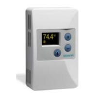
Figure 1. Temperature Room Unit.