Document No. 129-484
Installation Instructions
April 17, 2014
Information in this publication is based on current specifications. The company reserves the right to make changes in specifications and
models as design improvements are introduced. Product or company names mentioned herein may be the trademarks of their respective
owners. © 2014 Siemens Industry, Inc.
Building Technologies Division
1000 Deerfield Parkway
Buffalo Grove, IL 60089
USA
Your feedback is important to us. If you have
comments about this document, please send them to
SBT_technical.editor.us.sbt@siemens.com
Printed in the USA
Page 3 of 3
6. Do one of the following:
• If the cable is terminated: Inspect the RJ-11
connector for damage.
• If the cable is non-terminated or if the RJ-11
was damaged: Cut the cable, leaving about
three inches (75 mm) on the room unit side
of the drywall, and attach an RJ-11
connector with an RJ-11 crimping tool. On
the RJ-11 connectors, ensure that pin
Number 1 connects to the same wire at
each end of the cable. See Figure 3.
For retrofits: Before cutting the cable,
make sure it is disconnected from the
Temperature Room Unit port on the TEC
Figure 3. Terminating the RJ-11 Connector.
7. Plug the terminated cable into the RJ-11
connector on the back of the room unit's printed
circuit board (PCB).
8. Feed the extra cable back through the hole.
9. Snap the room unit cover to the room unit base
plate by first hooking the room unit front to the
top latches, and then rotating the cover
downward until it latches.
10. Loosen the safety set screw at the bottom of the
base one or two revolutions to lock the cover to
the base. Be careful not to loosen too far as the
screw can be completely removed from the
base.
11. Connect the room unit to the Temperature Room
Unit port on the TEC or ATEC.
The installation is now complete.
Electrical Box and Rough-in
Mounting, Typical
1. If a locator is attached to the rough-in device,
remove the locator by removing the two screws
and lightly rocking the locator to pull it free.
2. Untie the twist tie and pull about three inches
(75 mm) of the room unit cable through the hole
in the base plate.
3. Mount the room unit base plate on the wall,
noting the "UP" arrow:
NOTE: If required, position the Back Plate
behind the Room Unit Base, aligning the
top and bottom mounting holes, prior to
mounting to the wall:
a. Install the two room unit mounting screws
provided, but do not tighten.
b. Level the room unit base plate for
appearance only.
c. Tighten the two mounting screws to the
room unit base plate.
Over-tightening may cause the room unit
base plate to crack or bend.
4. Continue with Drywall Mounting (No Rough-in),
Typical, Steps 7 through 11.
The installation is now complete.
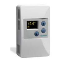
Set-up of Displayed Temperature
Units
displayed temperature
units is °F. To change
the display to °C mode,
snip the wire jumper on
the back of the PCB (the
visible side when the unit
is taken off the wall).
Figure 3.
 Loading...